Earth pressure balance shield machine cutterhead

An earth pressure balance and shield machine technology, which is applied in earth-moving drilling, mining equipment, tunnels, etc., can solve the problems of increasing the load of the cutter head motor, severe damage, and wear of the cutter head motor.

Active Publication Date: 2009-09-23
CHINA RAILWAY NO 2 ENG GRP CO LTD
View PDF0 Cites 15 Cited by
  • Summary
  • Abstract
  • Description
  • Claims
  • Application Information

AI Technical Summary

Problems solved by technology

When the sandy pebble formation contains strong weathered mudstone, if hobs are used for the entire surface, the tunneling efficiency will be reduced; and if there are too many toothed cutters, on the one hand, the excessive scraping resistance will increase the load on the cutter head motor, which will easily cause excessive wear of the cutter head motor; on the other hand On the one hand, because the mudstone is denser and harder than the sand and pebble formation, the tooth cutter wears very badly

Method used


Image

  • Earth pressure balance shield machine cutterhead
  • Earth pressure balance shield machine cutterhead
  • Earth pressure balance shield machine cutterhead

Examples


Embodiment 1

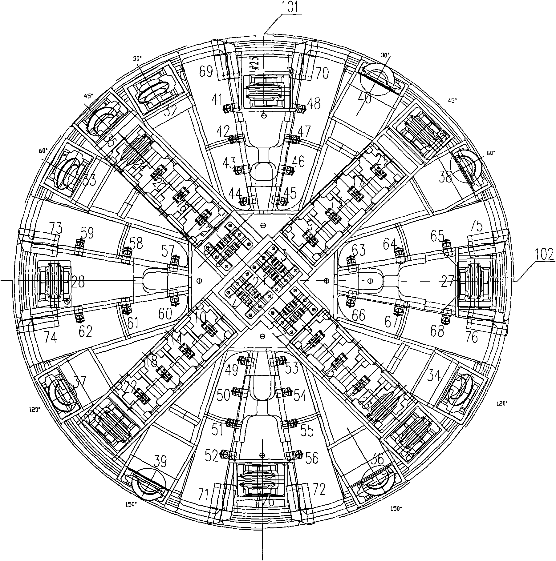
[0027] like figure 1 The cutter head of the earth pressure balance shield machine shown, the cutter head layout can be divided into the central area, the front area and the edge area.

[0028] Central area: Set 1#-8# knife holders, and double-edged toothed cutters are installed in the knife holders; taking the center of the cutterhead as the origin, the rotation radii of 1#-8# double-edged toothed cutters are 120mm, 170mm, 280mm, 340mm, respectively. 468mm, 542mm, 628mm, 705mm.

[0029] Front area: with the longitudinal cross line 101 of the cutter head as the center line, the 9#-31# knife holders are arranged in the 9#-31# knife seat at an angle of (±)45°; the cutter head is vertically and horizontally (0°, 90 °) A small scraper is arranged on the 41#-68# knife seat near the notch of the cross line (101, 102). Taking the center of the cutter head as the origin, the rotation radii of 9#-22# single-edged tooth cutters are 800mm, 900mm, 1000mm, 1100mm, 1200mm, 1300mm, 1400mm, ...

Embodiment 2

[0032] The difference with embodiment 1 is:

[0033] The 10#-14# knife holders and 16#-19# knife holders in the front area are arranged with single-edged tooth cutters, and the 9#, 15#, 20#-31# knife holders are arranged with double-edged hobs;

[0034] The 32-40# knife holders in the edge area are arranged with double-edged hobs, and the 69#-76# knife holders are arranged with side scrapers.

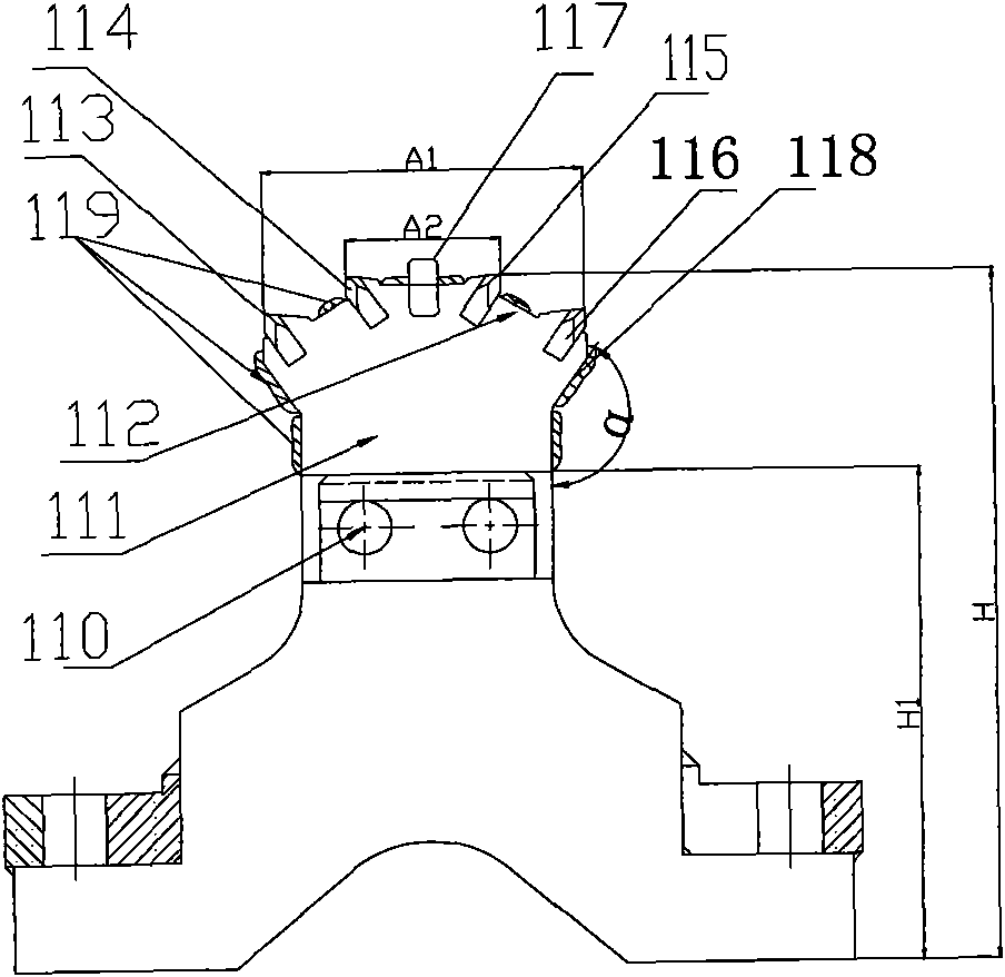
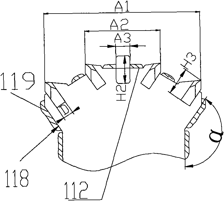
[0035] The double-edged serrated cutter described in above-mentioned embodiment 1 and 2 is as Figure 2-5 As shown, the lower parts of the two cutter heads 122 are respectively tightly fitted with the corresponding cutter body 121 by the bolts 110 and then welded to strengthen the connection strength between the cutter head and the cutter body. The knife body is fixedly connected in the knife seat. The cutter body height H1 is 277mm. The distance B between the outer surfaces 111 of the two cutter heads is 254mm, and the distance B2 between the inner surfaces 124 is 70mm; the length A...


PUM


Abstract

The invention discloses an earth pressure balance shield machine cutterhead. The surface of the cutterhead comprises a central area, a facial area and a marginal area, wherein each two-edged serrated cutter arranged on No. 1 to No. 8 cutter seats comprises two cutter bodies and two cutter heads fixedly connected on the cutter bodies, wherein the top face of each cutter head adopts the higher-middle and lower-side structure by gradually raising areas from both sides to the middle parts; the upper part of each side face of the cutter head is an externally expanded inclined face; the middle part of the top face is fixedly connected with a strip-shaped hard alloy, and the top faces of both sides of the strip-shaped hard alloy are fixedly connected with four rows of symmetrically distributed hard alloy column teeth; height differences are respectively formed between the tops of the hard alloy column teeth and the top of the strip-shaped hard alloy; and abrasion proof overlaying welding layers are fixedly connected with the peripheral top faces and the side faces of the strip-shaped hard alloy and the hard alloy column teeth. The cutterhead provided with the structure of the invention can increase advance rate, reduce abrasion and prolong service lives of the cutters, and reduce advancing cost under the circumstance of water-rich sandy cobble strata.

Description

technical field [0001] The invention relates to a cutter head of an earth pressure balance shield machine, in particular to the configuration of cutters on the cutter head. Background technique [0002] Due to its safety, speed and efficiency, shield construction has been more and more widely used in various underground engineering constructions such as urban subways, municipal public pipelines, oil / gas underground pipelines, etc. The surface of the cutter head of the existing shield machine includes a central area located at a 45-degree angle on both sides of the longitudinal or horizontal cross line of the cutter head, with the center of the cutter head as the origin, and a center area with a rotation radius of 0-705 mm. The radius of rotation within the 45-degree angle banners on both sides and between the banners near the notch is 705mm~2782mm. The front area is located at 30°, 45°, 60°, 120°, 150° angle banners and cutterheads on the side of the longitudinal cross line ...

Claims


Application Information

Patent Timeline
Patent Type & Authority Applications(China)
IPC IPC(8): E21D9/087
Inventor 李林陈强段绍和钟山刘向阳
Owner CHINA RAILWAY NO 2 ENG GRP CO LTD
Why Eureka
Try Eureka