Method and device for controlling inverter compressor

A frequency conversion compressor and control method technology, applied in the field of heating and ventilation, can solve the problems of not being able to adjust the frequency conversion speed according to the actual situation, and unable to realize a fast, energy-saving and stable frequency conversion process at the same time, so as to shorten the cooling time, ensure the stability, The effect of improving cooling efficiency

Inactive Publication Date: 2009-09-23
HAIER GRP CORP +1
6 Cites 84 Cited by

AI-Extracted Technical Summary

Problems solved by technology

[0005] In the prior art, no matter what frequency conversion method is used, since the fixed PID parameters are used in the frequency up process, it is only limited to a basically constant frequency conversion speed, and canno...

Method used

At present, magnetic levitation centrifugal compressor is subjected to the attention of air-conditioning, refrigeration industry day by day, and the bearing of this compressor centrifugal turbine adopts magnetic levitation bearing, because the friction between metal and metal does not exist in magnetic bearing, therefore does not need lubricating oil system, thereby It solves the technical problems that have plagued the industry for a long time, such as noise and lubrication, and the load efficiency of the magnetic levitation centrifugal compressor with frequency conversion control will be greatly improved. In the following several embodiments, the control method of the frequency conversion compressor of the present invention will be described in the background of a magnetic levitation centrifugal central air-conditioning unit.
In the present embodiment, the controller judges whether the difference between the actual temperature and the target temperature exceeds the limit value, and then adjusts the PID parameter, and the frequency converter changes the speed of frequency reduction, thereby realizing the stable control of the frequency reduction process , avoiding the low temperature protection of the unit caused by the low temperature of the outlet water, and ensuring the stability of the operation of the air conditioning unit.
The frequency conversion compressor con...

Abstract

The invention discloses a method for controlling an inverter compressor. According to the method, a target temperature and a dividing temperature point are preset, and a sensor monitors an actual temperature value. The method comprises the following steps that: a controller judges whether the difference between an actual temperature and the target temperature is zero, and the compressor operates at a minimum frequency for a certain period if the difference between an actual temperature and the target temperature is zero; the controller judges whether the target temperature is reached, and thecompressor stops operation if the target temperature is reached, or the controller initializes a PID parameter to allow an inverter to make the compressor start to raise frequency quickly if the target temperature is not reached; the controller judges whether the preset dividing temperature point is reached, and the PID parameter is adjusted if the preset dividing temperature point is reached, orthe PID parameter is kept constant if the reset dividing temperature point is not reached; and the controller judges whether the target temperature is reached, and the compressor operates at a constant frequency and the frequency inversion is finished if the target temperature is reached, or the compressor raises frequency while keeping the original PID parameter if the target temperature is not reached. Correspondingly, the invention also provides a device for controlling the inverter compressor. The method and the device can realize a quick, energy-saving and stable frequency inversion process at the same time.

Application Domain

Technology Topic

Constant frequencyEngineering +2

Image

  • Method and device for controlling inverter compressor
  • Method and device for controlling inverter compressor
  • Method and device for controlling inverter compressor

Examples

  • Experimental program(3)

Example Embodiment

[0034] Example one
[0035] This embodiment combines figure 2 , image 3 with Figure 4 A specific implementation of the control method of the inverter compressor of the present invention is disclosed.
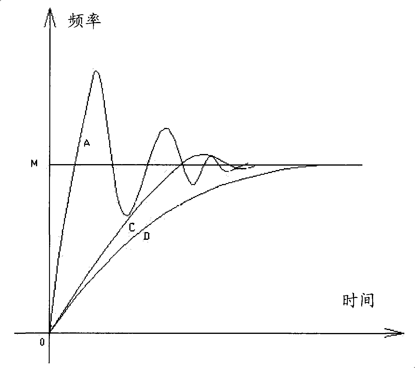
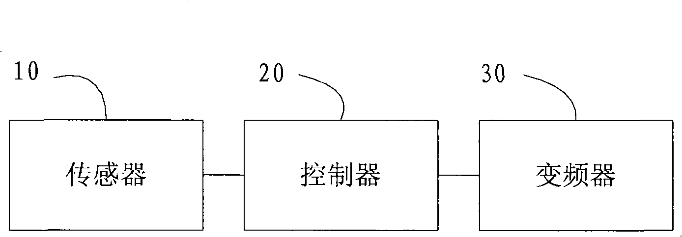
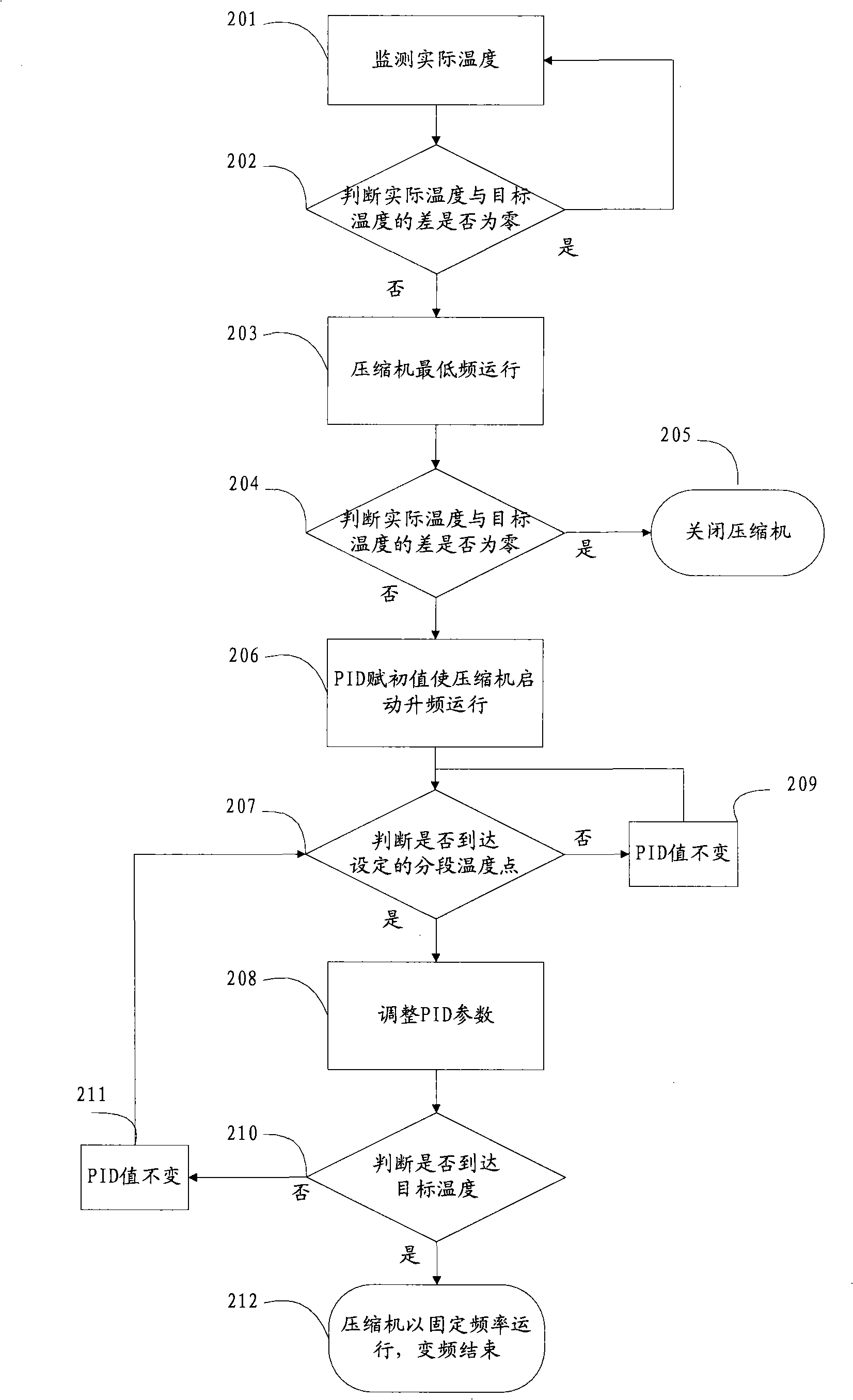
[0036] figure 2 It is a schematic diagram of the control device of the inverter compressor in this embodiment, image 3 It is a flowchart of the control method of the inverter compressor in this embodiment, Figure 4 It is a schematic diagram of the frequency conversion process of the compressor in this embodiment.
[0037] The refrigerant used in the frequency conversion magnetic levitation centrifugal air-conditioning unit is a common refrigerant in the refrigeration industry, and the refrigerant is water or other fluids. The unit compresses the refrigerant to cool the refrigerant first, and then circulates the refrigerant indoors to lower the room temperature, for example Use water as refrigerant, refer to figure 2 As shown, the inverter compressor control device includes: a sensor 10, a controller 20, and a frequency converter 30; the sensor 10 in the unit monitors the temperature of the outlet water in real time, and the controller 20 compares the measured actual temperature with the set target temperature. The PID parameter is set or adjusted to control the frequency change, and the frequency converter 30 is used to change the operating frequency of the compressor under the control of the controller 20.
[0038] Such as image 3 As shown, the target temperature is set to 0°C; according to step 201, the sensor 10 installed at the water outlet monitors the actual temperature value to obtain the difference between the actual temperature and the target temperature. For example, the sensor 10 detects that the current actual outlet temperature is 30°C, Then the difference ΔT between the actual temperature and the target temperature is 30°C.
[0039] Then according to step 202, it is judged whether the temperature difference between the actual temperature and the target temperature is zero. If it is, that is, the actual temperature is consistent with the target temperature, the compressor will not be started and the actual temperature will continue to be monitored; if not, the controller 20 will start according to step 203 The compressor runs at the lowest frequency; for example, if the temperature difference ΔT is 30°C greater than zero, the controller 20 controls the compressor to start and run at the lowest frequency for a period of time to make the compressor enter a stable state and prevent sudden start of high-frequency operation Cause the compressor to malfunction.
[0040]After running for a certain period of time at the lowest frequency with reference to step 204, the controller 20 obtains the current actual temperature from the sensor and determines whether the temperature difference between the current actual temperature and the target temperature is zero. If it is, it indicates that the required target temperature is reached, and the compressor is stopped. Such as step 205; if not, refer to step 206. The controller 20 assigns initial values ​​to the PID parameters. The inverter 30 controls the compressor to start up-frequency operation. The initial stage of the up-frequency operation has a higher speed in order to quickly obtain a large cooling capacity . For example, after the compressor runs at the lowest frequency for a certain period of time, the actual temperature drops from 30°C to 27°C, and the target temperature 0°C is not reached. Initial values ​​are assigned to the PID parameters, and the frequency starts to increase at a larger speed. The frequency changes like Figure 4 As shown by the middle curve EF, the compressor quickly rises to a higher frequency and reaches a larger cooling capacity.
[0041] After increasing the frequency at a higher speed for a period of time, refer to step 207 to determine whether the set segment temperature point is reached. If so, adjust the PID parameters to make the compressor run at different up-frequency speeds, as shown in step 208 If not, keep the original PID parameters, as shown in step 209. For example, it is preset to increase the frequency in four stages, and the three segment temperature points T1, T2, and T3 are respectively 23℃, 15℃, and 3℃. The sensor detects that the actual temperature drops to 23℃ and reaches the set segment temperature point. T1, at this time, the controller 20 adjusts the PID parameters, and the inverter 30 reduces the compressor's up-frequency speed, and the frequency changes as Figure 4 The middle curve FG is shown; when the sensor detects that the actual temperature drops to 15℃, it reaches the segmented temperature point T2. At this time, the controller 20 adjusts the PID parameters again, and the inverter 30 reduces the compressor's up-frequency speed again, and the frequency changes as Figure 4 As shown by the middle curve GH, the frequency change tends to be stable; against the gradual increase in the cooling capacity, the actual temperature drops to 3°C and reaches the set segment temperature point T3. The controller 20 adjusts the PID parameters again, and the frequency changes as Figure 4 As shown by the middle curve HM, the frequency converter 30 is controlled to further reduce the compressor up-frequency speed, increase the cooling capacity more gently, and approach the target temperature.
[0042] Referring to step 210, the controller judges whether the target temperature is reached according to the actual temperature monitored by the sensor 10. If it is, then in step 212, the compressor runs at a fixed frequency and the frequency conversion ends; if not, in step 211, the original PID parameters are maintained Increase the frequency at a fixed speed of the compressor, and then return to step 207. For example, the sensor 10 detects that the actual temperature is 0°C and reaches the target temperature, the frequency converter 30 stops the frequency conversion, and the compressor runs at a fixed frequency.
[0043] In this embodiment, the up-conversion process is divided into four stages with the temperature point as the limit, and the PID parameters are changed in each stage to adjust the speed of the frequency conversion; Figure 4 In the EF stage, the frequency is increased at a higher speed, and a larger cooling capacity is quickly obtained. At this time, the temperature change rate is also larger. Then, when the actual temperature reaches the segment temperature point of 23°C, adjust the PID parameters to reduce the increase. Frequency speed, such as Figure 4 During the FG stage, the cooling capacity growth rate also slows down, and the actual temperature continues to decrease; when the actual temperature reaches the next segment temperature point of 15°C, adjust the PID parameters to further reduce the frequency increase speed, such as Figure 4 In the GH stage, the growth rate of the cooling capacity is further reduced, and the temperature change tends to be slow, so as to steadily approach the target; Figure 4 In the HM stage, the actual temperature reaches the segmented temperature point of 3°C, which is close to the target temperature. Adjust the PID parameters to make the frequency increase speed tend to zero and slowly approach the required temperature, thereby preventing overshoot and avoiding frequent frequency lifting. Figure 4 The middle shaded part represents the integral area of ​​the curve EGHHM, which corresponds to the energy consumption in the frequency conversion process, which can be seen relative to figure 1 The frequency conversion control method in the prior art has a smaller integral area and is more energy-saving.
[0044] The inverter compressor control method described in this embodiment, compared to several inverter control methods in the prior art, adjusts the inverter process in stages, starts a rapid frequency increase, improves the refrigeration efficiency, and then gradually reduces the frequency increase speed, slowly approaching The target temperature prevents overshoot, avoids frequent frequency up and down, shortens the cooling time as a whole, and saves energy.
[0045] In the frequency-up process of the first embodiment, as the compressor frequency increases, the cooling capacity also increases, and the temperature decreases rapidly. If the temperature change rate is too large, the suction pressure of the unit system is too low or the discharge pressure is too high , May cause unit failure. In order to avoid such conditions and ensure stable operation of air-conditioning unit, the inverter compressor control method of the present invention also includes setting a limit value of temperature change rate, and the controller depends on whether the actual temperature change rate exceeds the limit value Adjust PID parameters, which are specifically described in the following embodiments.

Example Embodiment

[0046] Example two
[0047] This embodiment combines with Figure 5-Figure 7 Another specific implementation of the inverter compressor control method is disclosed. The difference from the first embodiment is that after adjusting the PID parameters in sections, the controller detects in real time whether the temperature change rate exceeds the limit value, and if so, re-assigns the PID parameters until the temperature change rate is lower than the limit value.
[0048] Figure 5 It is a schematic diagram of the control device of the inverter compressor in this embodiment, Figure 6 It is a flowchart of the control method of the inverter compressor in this embodiment, Figure 7 It is a schematic diagram of the frequency conversion process of the compressor in this embodiment.
[0049] Reference Figure 5 As shown, the inverter compressor control device includes: a sensor 11, a controller 21, and a frequency converter 31; the sensor 11 in the unit monitors the outlet water temperature in real time, and the controller 21 compares the measured actual temperature with the set target temperature. Set or adjust the PID parameters to control the frequency change. The controller 21 is also used to monitor the real-time temperature change rate and determine whether the actual temperature change rate exceeds the limit value. If so, adjust the PID parameters to reduce the temperature change rate, and the inverter 31 Used to change the compressor operating frequency under the control of the controller 21.
[0050] Such as Figure 6 As shown, the target temperature is set to 0°C, and the frequency is pre-set in five stages. The four temperature points T1, T2, T3, and T4 are respectively 20°C, 13°C, 7°C, and 3°C; follow step 301 , The sensor 11 arranged at the water outlet monitors the actual temperature value to obtain the difference between the actual temperature and the target temperature. For example, the sensor 11 monitors that the current actual water outlet temperature is 30°C, then the difference ΔT between the actual temperature and the target temperature is 30°C.
[0051] Then according to step 302, it is judged whether the temperature difference between the actual temperature and the target temperature is zero. If it is, that is, the actual temperature is consistent with the target temperature, the compressor will not be started and the actual temperature will continue to be monitored; if not, it indicates that the compressor needs to be started for cooling, then According to step 303, the controller 21 starts the compressor to run at the lowest frequency for a period of time; for example, if the temperature difference ΔT is 30°C greater than zero, the controller 21 starts to start the compressor and runs at the lowest frequency for a period of time, so that the compressor is stable State to prevent compressor malfunction caused by sudden start of high frequency operation.
[0052] Similar to the first embodiment, after the compressor runs at the lowest frequency for a certain period of time, the controller 21 obtains the current actual temperature from the sensor and determines whether the temperature difference between the current actual temperature and the target temperature is zero. If it is, it indicates that the required target temperature is reached. Then stop the compressor operation; if not, indicating that the cooling capacity still needs to be increased, the controller 21 assigns an initial value to the PID parameter, and the inverter 31 controls the compressor to start the up-frequency operation. The speed at the beginning of the up-frequency is higher so that Get a lot of cooling capacity quickly. For example, after the compressor runs at the lowest frequency for a certain period of time, the actual temperature drops from 30°C to 27°C, and the target temperature 0°C is not reached. Initial values ​​are assigned to the PID parameters, and the frequency starts to increase at a larger speed. The frequency changes like Figure 7 As shown by the middle curve E’F’, the compressor quickly rises to a higher frequency and reaches a larger cooling capacity.
[0053] After increasing the frequency at a higher speed for a period of time, refer to step 304 to determine whether the set segment temperature point has been reached. If so, adjust the PID parameters as shown in step 306 to make the compressor increase step by step at different speeds. If not, keep the original PID parameters, as shown in step 305. For example, the sensor detects that the actual temperature drops from 27°C to 20°C and reaches the set segment temperature point T1. At this time, the controller 21 adjusts the PID parameters, and the inverter 31 reduces the compressor's up-frequency speed, and the frequency changes as Figure 7 The middle curve F'G' is shown; when the sensor 11 detects that the actual temperature drops to 13°C, it reaches the segmented temperature point T2. At this time, the controller 21 adjusts the PID parameters again, and the frequency converter 31 reduces the compressor's up-frequency speed again , The frequency changes as Figure 7 As shown by the middle curve G'H', the frequency change tends to be stable; against the gradual increase in cooling capacity, the actual temperature drops to 7°C, reaching the set segment temperature point T3, the controller 21 adjusts the PID parameters again, and the frequency changes Such as Figure 7 As shown by the middle curve H'M', the inverter 31 is controlled to further reduce the compressor's up-frequency speed, increase the cooling capacity more gently, and approach the target temperature; finally, the actual temperature drops to 3°C, which is very close to the target temperature. At T4, the controller changes the PID parameters to reduce the frequency increase speed as much as possible, and the cooling capacity slowly increases, gradually approaching the target temperature, effectively preventing overshoot.
[0054] Referring to step 307, the controller 21 monitors the real-time temperature change rate. After each PID parameter adjustment, if the temperature change rate exceeds the preset limit value, in order to avoid the unit system failure, the controller 21 returns to step 306 to readjust the PID Parameters, and then monitor whether the real-time temperature change rate exceeds the limit value until the temperature change rate is normal to ensure stable operation of the air conditioning unit.
[0055] If the temperature change rate does not exceed the limit value after the controller adjusts the PID parameters, then follow step 308 to determine whether the target temperature is reached, if yes, follow step 310, the compressor runs at a fixed frequency, and the frequency conversion ends; if not, follow step 309. Keep the original PID parameters to increase the fixed speed of the compressor, and then return to step 304. For example, the sensor 11 detects that the actual temperature is 0°C and reaches the target temperature, the frequency converter 31 stops the frequency conversion, and the compressor runs at a fixed frequency.
[0056] In this embodiment, the up-conversion process is divided into five stages based on the temperature point, each stage changes the PID parameters to adjust the speed of the frequency conversion; Figure 7 In the E'F' stage, the frequency is increased at a higher speed, and a larger cooling capacity is quickly obtained. At this time, the temperature change rate is also larger, and then when the actual temperature reaches the segment temperature point of 20°C, adjust the PID parameters , Reduce the speed of upscaling, such as Figure 7 In the F’G’ stage, the cooling capacity growth rate also slows down accordingly, and the actual temperature continues to decrease; when the actual temperature reaches the next segment temperature point of 13°C, adjust the PID parameters to further reduce the frequency increase speed, such as Figure 7 In the G’H’ stage, the growth rate of cooling capacity is further reduced, and the temperature change tends to be slow, so as to steadily approach the target; Figure 7 In the H'M' stage, the actual temperature reaches the segmented temperature point of 7°C, which is close to the target temperature. Adjust the PID parameters to make the frequency increase speed continue to decrease and slowly approach the required temperature; finally the actual temperature reaches the segmented temperature point of 7°C, adjust PID parameters minimize the speed of up-frequency, such as Figure 7 In the M’N’ stage, to prevent overshoot and avoid frequent frequency fluctuations. Figure 7 The middle shaded part represents the integral area of ​​the curve E’F’G’H’M’N’, which corresponds to the energy consumption in the frequency conversion process. figure 1 The frequency conversion control method in the prior art has a smaller integral area and is more energy-saving.
[0057] Compared with the several frequency conversion control methods in the prior art, the frequency conversion compressor control method described in this embodiment improves the refrigeration efficiency by adjusting the frequency conversion process in stages, avoids frequent frequency up and down, and saves energy; Yes, the controller monitors the temperature change rate in real time, which effectively prevents the temperature change rate from exceeding the limit value and ensures the stability of the system operation.
[0058]In addition, compared with the first embodiment, the five-stage up-conversion process in this embodiment can also realize a fast, energy-saving and stable frequency conversion process. Those skilled in the art should be able to easily infer that the process is divided into at least three stages and more than three stages. All of the frequency up-conversion processes can achieve the purpose of the present invention and also belong to the protection scope of the present invention.
[0059] The inverter compressor control method and device of the present invention can also reduce the refrigeration capacity by adjusting the PID parameters to reduce the compressor frequency, so as to avoid the low temperature protection of the unit caused by the low temperature of the outlet water, which is specifically described in the following embodiments.

Example Embodiment

[0060] Example three
[0061] This embodiment combines with Figure 8 with Picture 9 Another embodiment of the inverter compressor control method is disclosed. In the refrigeration process, if the actual temperature is lower than the target temperature, that is, the actual temperature is over-adjusted relative to the target temperature, the inverter compressor control method and device described in this embodiment determines whether the over-adjustment is over, and then starts the down-frequency adjustment process.
[0062] Figure 8 It is a schematic diagram of the control device of the inverter compressor in this embodiment, Picture 9 It is a flowchart of the control method of the inverter compressor in this embodiment.
[0063] Reference Figure 8 As shown, the control device of the inverter compressor includes: a sensor 12, a controller 22, and a frequency converter 32; wherein the sensor 12 is used to monitor the temperature of the outlet water in real time, and the controller 22 is used to measure the actual temperature and the set temperature. After the target temperature is compared, the PID parameters are set or adjusted to control the frequency change, and it is also used to monitor whether the actual temperature is lower than the target temperature. If it is, it indicates that the frequency is over-adjusted, and then the frequency is reduced. If not, the compressor runs at a fixed frequency When the frequency conversion ends, the compressor runs at a fixed frequency, and the frequency converter 32 is used to change the operating frequency of the compressor under the control of the controller 22.
[0064] Such as Picture 9 As shown, after the frequency up process, the compressor runs at a fixed frequency, as in step 401; the sensor 22 monitors the actual outlet water temperature, and according to step 402, the controller 32 determines whether the actual temperature is lower than the target temperature. If it is, it indicates that the cooling capacity is too large. Then re-assign the PID parameters as shown in step 403, the inverter 32 starts to reduce the frequency, if not, the compressor continues to run at a fixed frequency; according to step 404, the controller 22 determines whether the difference between the actual temperature and the target temperature exceeds the preset value If it is, adjust the PID parameters to quickly reduce the frequency as shown in step 406, and quickly reduce the cooling capacity to avoid low temperature protection of the unit due to the low temperature of the outlet water, thereby ensuring the stable operation of the air conditioning unit; if it does not exceed the preset For the limited value, the PID parameters are kept unchanged as shown in step 405, and the frequency is reduced at a fixed speed.
[0065] In this embodiment, the controller judges whether the difference between the actual temperature and the target temperature exceeds the limit value, and then adjusts the PID parameters, and the inverter changes the speed of frequency reduction, thereby achieving stable control of the frequency reduction process and avoiding The outlet water temperature is too low to cause low temperature protection of the unit to ensure the stability of the air conditioning unit.

PUM

no PUM

Description & Claims & Application Information

We can also present the details of the Description, Claims and Application information to help users get a comprehensive understanding of the technical details of the patent, such as background art, summary of invention, brief description of drawings, description of embodiments, and other original content. On the other hand, users can also determine the specific scope of protection of the technology through the list of claims; as well as understand the changes in the life cycle of the technology with the presentation of the patent timeline. Login to view more.

Similar technology patents

Classification and recommendation of technical efficacy words

  • Avoid overshoot
  • Improve cooling efficiency

Composite control method for piezoelectric ceramic positioning

InactiveCN102621889AAvoid overshootQuick responseAdaptive controlCeramicElectricity
Owner:INST OF OPTICS & ELECTRONICS - CHINESE ACAD OF SCI

Motor control method and device, terminal and storage medium

Owner:SHENZHEN INST OF ADVANCED TECH CHINESE ACAD OF SCI
Why Eureka
Try Eureka