Hall difference equation force measuring method for symmetrical and complementary structure

A symmetrical and force-measuring technology, which is applied in the measurement of fluid pressure involving magnet displacement, the measurement of elastic deformation force through measuring gauges, and the use of electric/magnetic devices to transmit sensing components, etc., can solve the problem of non-linear factors that cannot be eliminated , There are no problems such as non-contact measurement, high magnet size requirements, etc., to achieve the effect of convenient application, offsetting DC component and zero temperature drift, and simple interface

Inactive Publication Date: 2009-09-23
邱召运
View PDF1 Cites 16 Cited by
  • Summary
  • Abstract
  • Description
  • Claims
  • Application Information

AI Technical Summary

Problems solved by technology

The analysis found that this method has great limitations and has high requirements on the size of the magnet, especially when the magnet or Hall element rotates, it cannot eliminate the influence of nonlinear factors, so it is only suitable for the linearity of the small displacement of the elastic body. Variety
In addition, the Hall element is fixed on the elastic body, and the non-contact measurement is not really realized, so the application is limited

Method used


Image

  • Hall difference equation force measuring method for symmetrical and complementary structure
  • Hall difference equation force measuring method for symmetrical and complementary structure
  • Hall difference equation force measuring method for symmetrical and complementary structure

Examples


Embodiment Construction

[0030] 1. The structure and working principle of the force measurement model

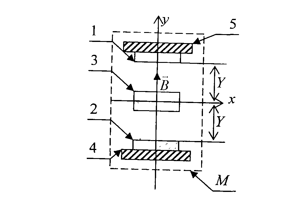
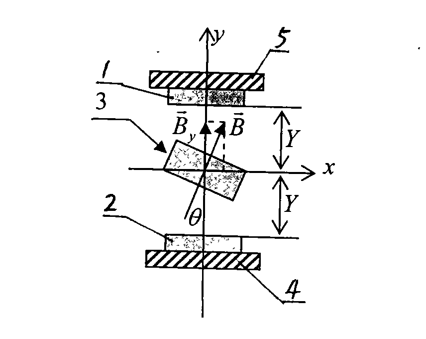
[0031] See attached figure 1 , the model structure of the Hall differential force measuring method with a symmetrical complementary structure is shown in part M, and the Hall element H 1 and Hall element H 2 Symmetrically placed outside the two ends of the cylindrical permanent magnet 3, the Hall element H 1 and Hall element H 2 The sensitive center of the cylinder is on the same axis as the center of the cylindrical permanent magnet 3, and the Hall element H 1 and Hall element H 2 The faces of the character logos are in the same direction, and they all face the opposite direction of the y-axis and are perpendicular to the y-axis. The center of the cylindrical permanent magnet 3 is located on the coordinate origin, and the y-axis is consistent with the axis of the cylindrical permanent magnet 3. In the initial state, the Hall element H 1 and Hall element H2 The distance from the coordinate ori...


PUM


Abstract

The invention discloses a Hall difference equation force measuring method for a symmetrical and complementary structure. The method comprises the following steps: (1) fixing a cylindrical permanent magnet on an elastic body, symmetrically arranging two linear Hall elements on both sides of the cylindrical permanent magnet without moving along the elastic body so as to ensure that the facing direction of the character sign surfaces of the two linear Hall elements are consistent and parallel to both end faces of the cylindrical permanent magnet and then connecting the two Hall elements into a measuring circuit; (2) applying force F to the elastic body of the step (1) so as to ensure that the cylindrical permanent magnet generates displacement change and recording an output voltage difference value of the two linear Hall elements, wherein the voltage difference value is expressed by delta U; and (3) substituting the delta U value obtained in the step (2) into the formula delta U=delta U0+2KF so as to solve the value of the applied force F, wherein the delta U0 in the formula is a static output voltage difference value of the two linear Hall elements, and K is a linear coefficient. The method has good linearty and higher sensitivity.

Description

technical field [0001] The invention relates to a Hall differential force measuring method with a symmetrical complementary structure, which belongs to the technical field of sensors and measurements, and is mainly used for non-contact force measurement. Background technique [0002] Most of the commonly used force sensors use strain gauges as sensitive elements. The method is to fix multiple strain gauges on the elastic body. The strain gauges form a Wheatstone bridge circuit. When the strain gauges deform with the elastic body, the resistance of the strain gauges The value changes to realize the conversion from mechanical quantity to electrical quantity. This strain-type method has been used for a long time, and it is mainly used in force sensors at present. The disadvantage of the strain type is that the sensitive element is in direct contact with the elastic body. When the elastic body deforms greatly, it will cause permanent damage to the strain gauge. Therefore, it ha...

Claims


Application Information

Patent Timeline
Patent Type & Authority Applications(China)
IPC IPC(8): G01L1/04G01D5/12G01L9/14
Inventor 邱召运
Owner 邱召运
Why Eureka
Try Eureka