Electronic equipment connected with USB adapter
A technology of electronic equipment and connecting line, which is applied to the field of electronic equipment connected with a USB connector, can solve the problems of inconvenience to carry, reduce the volume, and increase the size of the equipment, and achieve the effects of convenient use and carrying, increased firmness, and convenient use.
- Summary
- Abstract
- Description
- Claims
- Application Information
AI Technical Summary
Problems solved by technology
Method used
Image
Examples
Embodiment 1
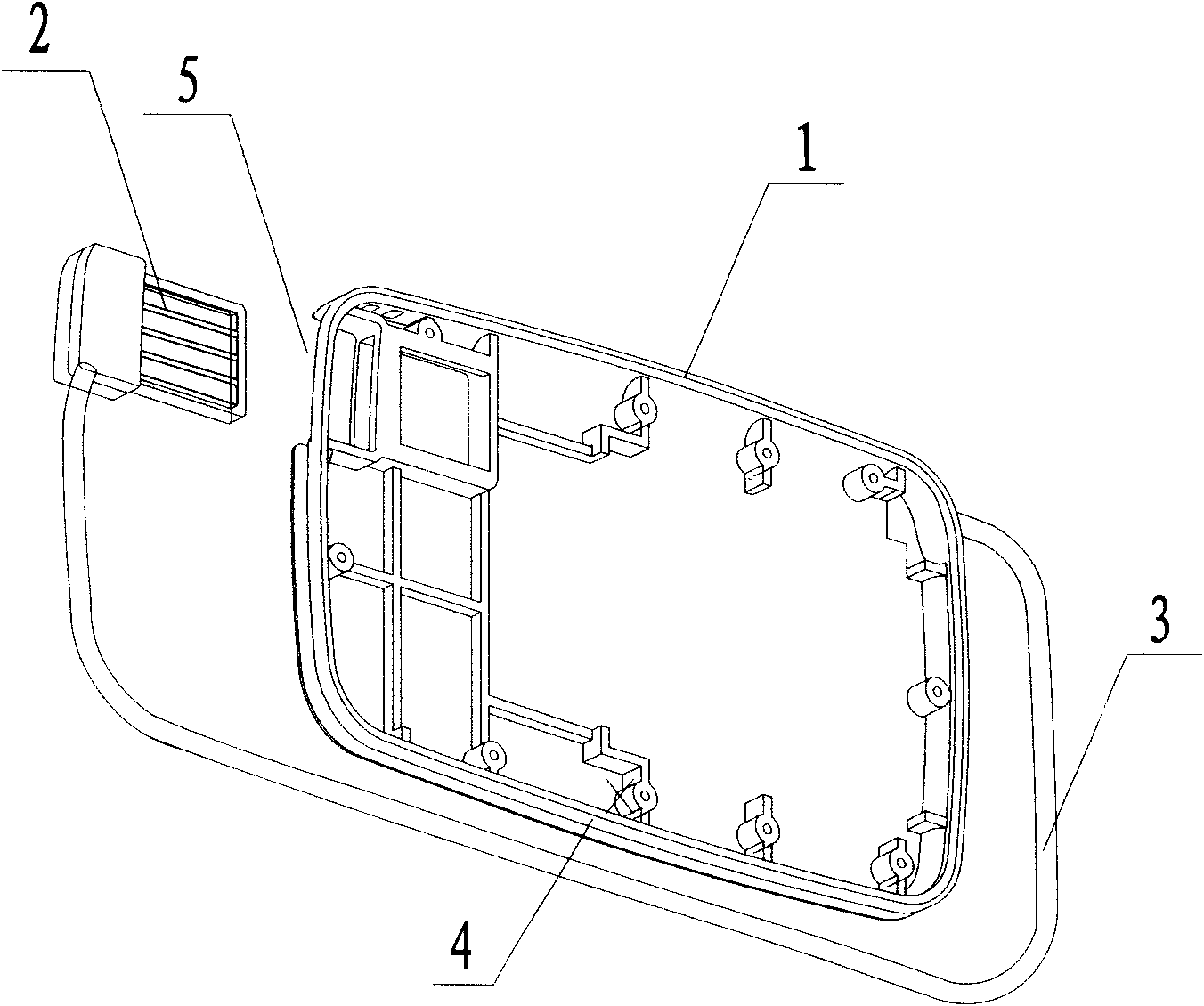
[0043] Such as figure 1 The electronic device connected with the USB connector shown includes: a body shell 1, a USB connector 2 and a connecting line 3, and the body shell 1 is used to accommodate and carry various components, such as a circuit board, a liquid crystal screen, and an operation panel One end of the connection line 3 is a connection end, and the connection end is electrically connected to the electronic components in the body casing 1 , and the other end of the connection line 3 is connected to the USB connector 2 .
[0044]The fuselage shell 1 has a certain thickness, so that electronic components can be arranged in the fuselage shell 1 . The thickness is greater than the diameter of the connecting wire 3, and a groove 4 for accommodating the connecting wire 3 and an accommodating portion for accommodating the USB connector 2 are opened on the outer wall of the body casing 1, and the accommodating portion is a The slot 5 , the slot 5 and the connection line 3 ...
Embodiment 2
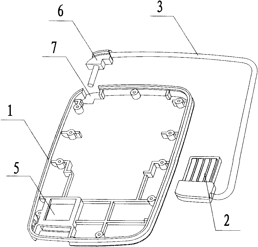
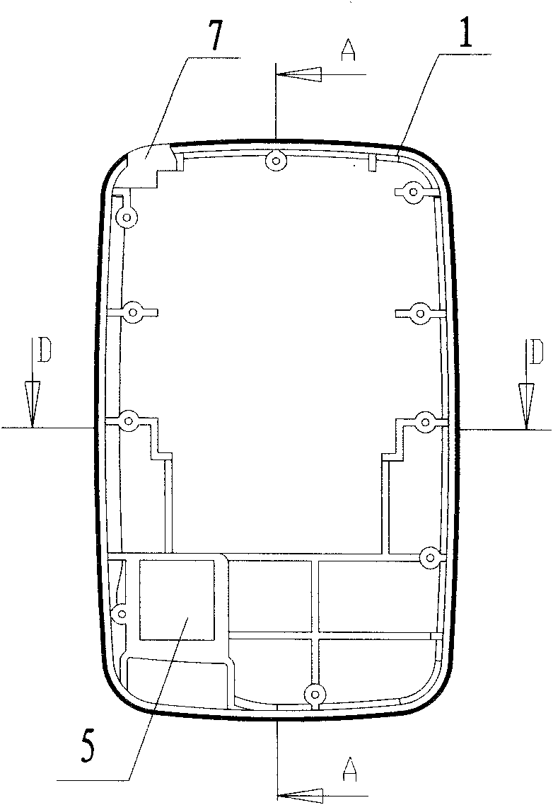
[0046] Such as Figure 2 to Figure 5 As shown in the electronic device connected with a USB connector, the difference between this embodiment and the first embodiment is that a block 6 is provided at the connection end of the connection line 3, and a block 6 is opened inside the block 6 for the connection line. 3 through the space; the outer wall of the fuselage shell 1 is provided with a slot 7 that is adapted to the shape of the block 6 and is used to hold the block 6 . Such as Figure 5 As shown, the space inside the block 6 for the connecting wire 3 to pass through is a through hole (not shown in the figure). The card slot 7 is located at a corner of the fuselage shell 1, and the through hole in the card block 7 is arranged in an arc shape, so as to limit the turning of the connecting line 3 in the through hole, which is beneficial to Protect the connecting wire 3 .
Embodiment 3
[0048] Such as Image 6 The difference between the present embodiment and the second embodiment of the illustrated electronic device connected with a USB connector is that the space provided in the block 6 for the connection line 3 to pass through is not a through hole, but a space in the block 6 . A notch 10 is provided directly to the inside of the block from two surfaces facing the body shell 1 , and the connecting end of the connecting wire 3 passes through the notch 10 . Another difference from Embodiment 2 is that threaded holes 9 are provided at the corresponding positions of the card slot 7 and the card block 6, and the card block 6 is connected with the body shell 1 by screws 8, which is convenient The clamping block 6 is disassembled from the fuselage shell 1. In addition, the connecting wire 3 is located in the notch space between the screw 8 and the clamping block 6, so that the screw 8 not only plays the role of positioning, but also plays a role in positioning th...
PUM
 Abstract
Description
Claims
Application Information
 - R&D
- Intellectual Property
- Life Sciences
- Materials
- Tech Scout
- Unparalleled Data Quality
- Higher Quality Content
- 60% Fewer Hallucinations
Browse by: Latest US Patents, China's latest patents, Technical Efficacy Thesaurus, Application Domain, Technology Topic, Popular Technical Reports.
© 2025 PatSnap. All rights reserved.Legal|Privacy policy|Modern Slavery Act Transparency Statement|Sitemap|About US| Contact US: help@patsnap.com


