Catenary-less transportation system and its charging method

一种交通系统、充电方法的技术,应用在充电站、电动汽车充电技术、集电器等方向,能够解决增加地面侧和车辆侧成本、部件构造复杂化等问题,达到降低安装成本、减轻重量、减少所需数量的效果

Inactive Publication Date: 2009-09-23
MITSUBISHI HEAVY IND ENG CO LTD
View PDF0 Cites 17 Cited by
  • Summary
  • Abstract
  • Description
  • Claims
  • Application Information

AI Technical Summary

Problems solved by technology

Therefore, there may be a problem of complicating the construction of parts and increasing the cost on the ground side and the vehicle side

Method used


Image

  • Catenary-less transportation system and its charging method
  • Catenary-less transportation system and its charging method
  • Catenary-less transportation system and its charging method

Examples


Embodiment 1

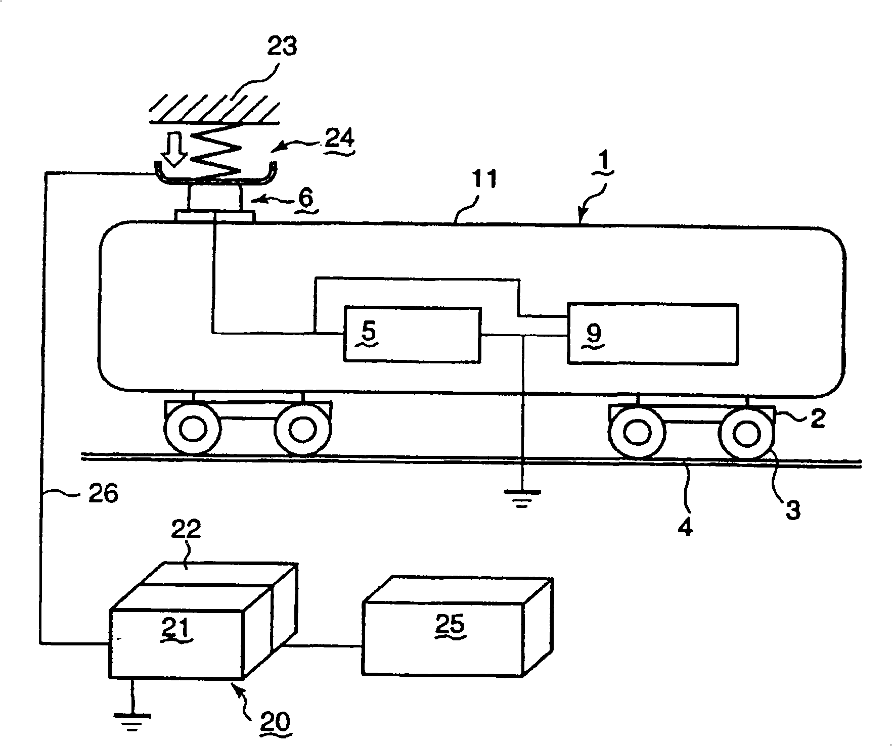
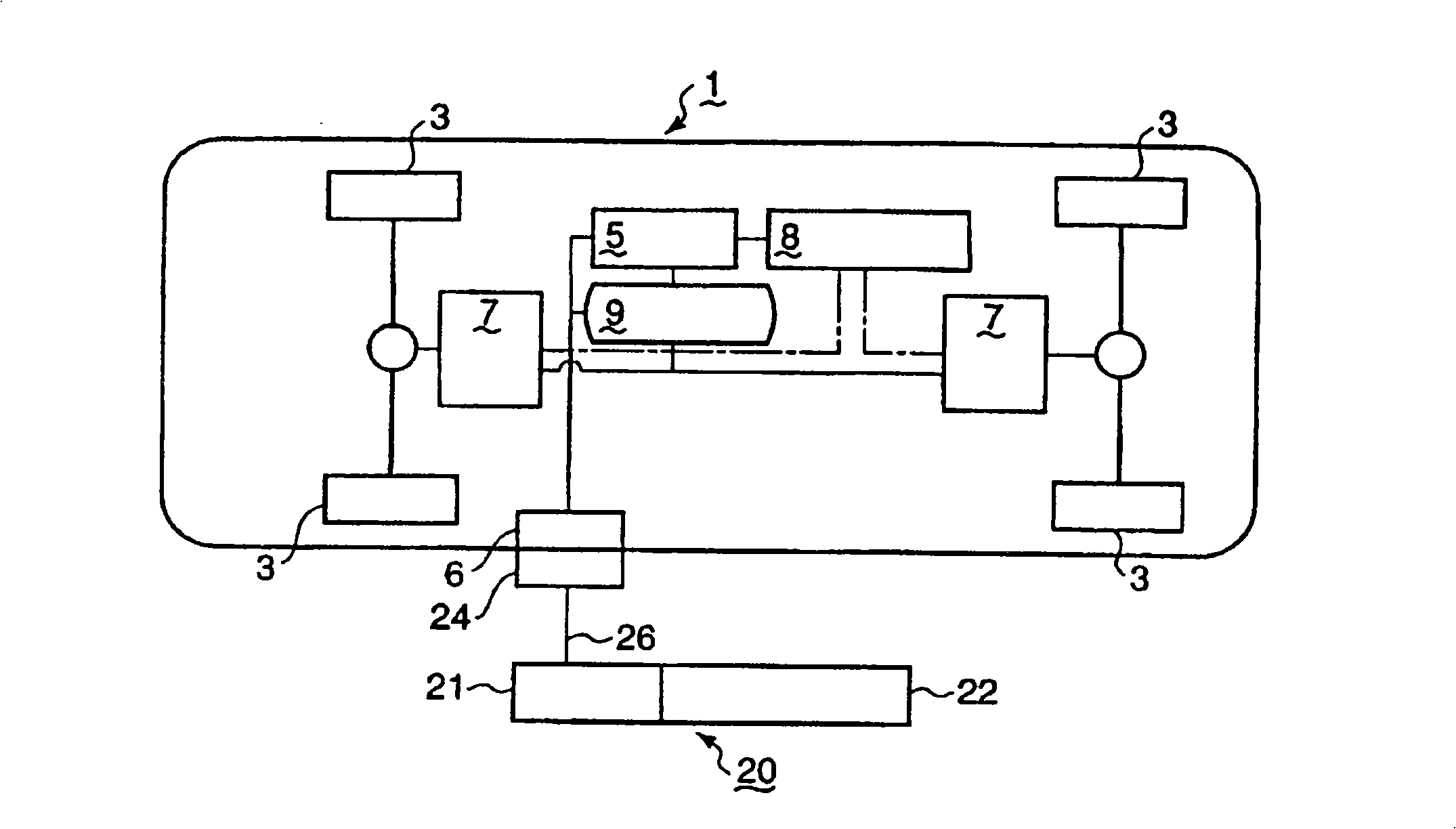
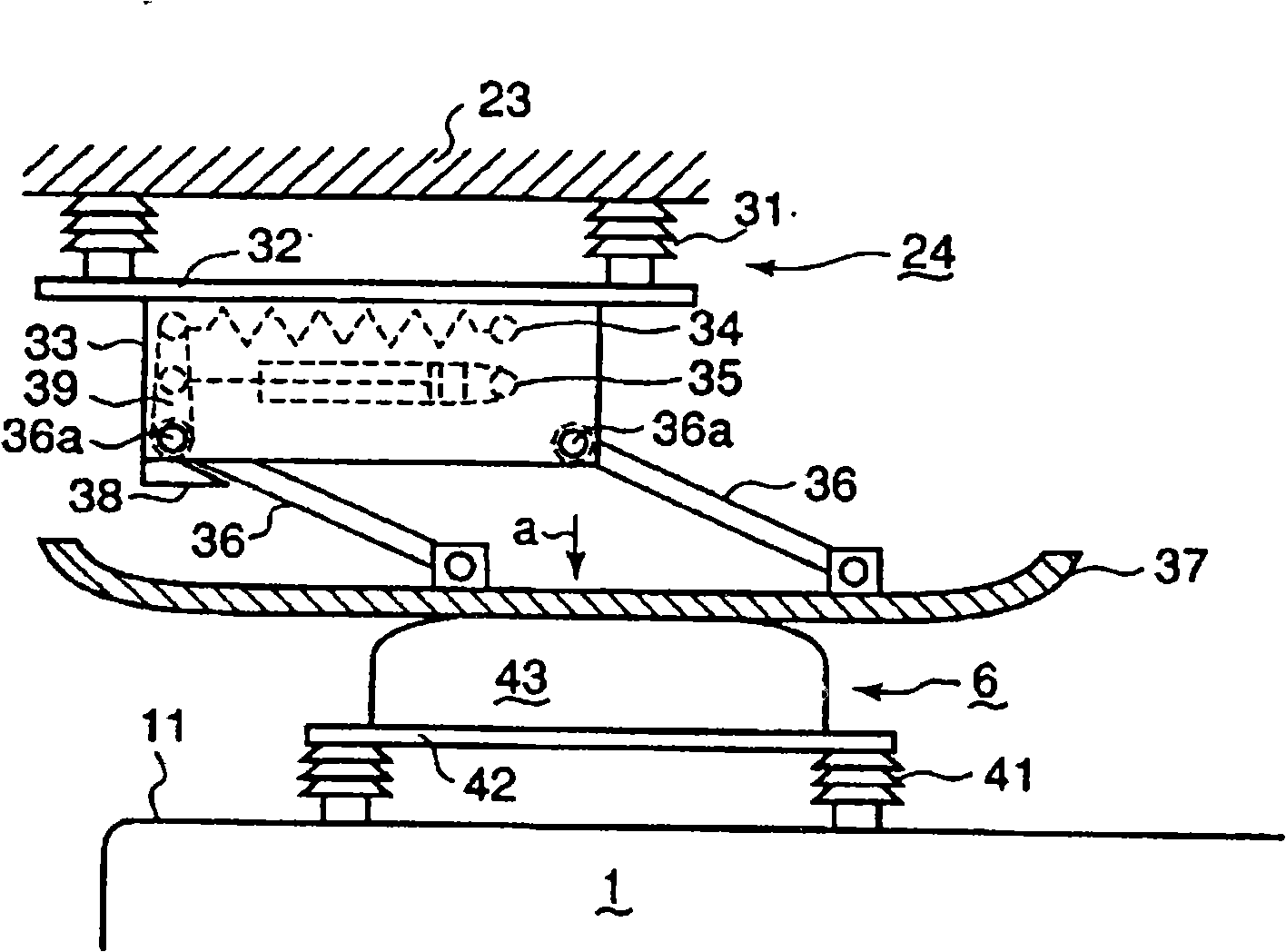
[0046] will refer to Figure 1 to Figure 4 A first embodiment of the present invention is described, in which figure 1 is a schematic diagram generally showing the feederless traffic system in this embodiment, figure 2 is a block diagram showing the control system in this embodiment, image 3 is a partially enlarged front view showing the power feeder and the power receiver in this embodiment, Figure 4 is a flowchart for describing the operation steps in this embodiment.

[0047] refer to figure 1 , the vehicle 1 includes a bogie 2 having wheels 3, and in addition, the vehicle 1 has a storage battery 5 mounted thereon, adapted to be supplied with electric power from a charging device 20 provided on the ground when the vehicle 1 stops at a station or the like, so as to Drive on track 4. The charging device 20 provided at a station or the like includes a charger 21 that converts commercial power supplied from a transformer station 25 into a DC (direct current) voltage suc...

Embodiment 2

[0064] Next, we will refer to Figure 5 with 6 A second embodiment of the present invention is described, wherein, Figure 5 is a plan view showing the power feeder and the power receiver in this embodiment, and Image 6 is viewed in the vertical direction along the Figure 5 An illustration of the line A-A in. refer to Figure 5 with 6 , in the power receiver 60 fixed on the roof 11 of the vehicle 1, the support frame 62 is supported horizontally on the roof 11 of the vehicle 1 through the intermediary of the insulator 61, and a plane contactor 63 is installed thereon, which stands upright on the support The frame 62 extends along the forward direction b of the vehicle.

[0065] Meanwhile, in the power feeder 50 , the support frame 53 is arranged along each aboveground structure 51 provided on the opposite side of the contactor 63 through the intermediary of the insulator 52 in the vehicle advancing direction b. Two links 55 are rotatably attached to the outer surface ...

Embodiment 3

[0070] Next, we will refer to Figure 7 A third embodiment of the present invention is described, in which Figure 7 is a schematic diagram showing the entire feederless traffic system in this embodiment. refer to Figure 7 , three power feeders 24 a to 24 c are provided on the ground structure 23 along the track 4 . With this embodiment, a plurality of vehicles 1a to 1c can be simultaneously charged by a group of charging devices 20 provided on the ground.

[0071] It should be noted that, in the present embodiment, the power storage units on a plurality of train-type vehicles can be charged from one power source, and vehicles with less remaining power can be preferentially automatically charged by constant current charging. In addition, the state of charge can be detected so that a vehicle with less remaining electric power can be selected and charged.

[0072] Furthermore, the power receiver of the vehicle in which the power storage unit has been charged up to the set c...


PUM


Abstract

Provided is a railway type feeder-lineless traffic system in which the weight of a vehicle is reduced while the structure of the vehicle is simplified, and it is possible to carry out a quick charge during a brief stopping time at a station or the like. A charging method in a feeder-lineless traffic system in which a vehicle mounted thereon with an electric storage unit runs on a predetermined pathway with the use of a power, and the electric storage unit in the vehicle is charged from a charger set up on the pathway, wherein a contact charging way in which a power feeder 24 connected to the charger 21 set up on the ground is made into contact with a power receiver 6 mounted on a vehicle 1 is carried out when the vehicle 1 comes to a stop, and a commercial electric power is converted by the charger and a charge control unit of the charger into a DC power which is chargeable direct into the electric storage unit 1, and the DC power is quickly charged into the electric storage unit through the intermediary of the power feeder and the power receiver while a current value of the DC power is controlled.

Description

technical field [0001] The present invention relates to a feederless transportation system in which a vehicle on which an electric storage unit is provided travels on a predetermined route such as a track while receiving electric power from a ground charging device; and thus relates to a charging method thereof, and in which the charging The control unit is placed on the ground in order to reduce the weight of the vehicle and simplify the construction of the vehicle. Background technique [0002] In recent years, as a transportation system for running vehicles on predetermined tracks, a feederless transportation system using a trolley that can run without power supply from an overhead line has been proposed. Trams in feederless traffic systems have electric storage units installed therein. [0003] For example, Patent Document 1 (Japanese Patent Laid-Open No. 2000-83302) discloses a feederless transportation system as described above. [0004] In the transportation system ...

Claims


Application Information

Patent Timeline
Patent Type & Authority Applications(China)
IPC IPC(8): B60L13/00B60L11/18
CPCB60L2200/26B60L11/185B60M1/36B60L9/00B60L11/1816Y02T90/14B60L5/42Y02T90/121Y02T10/7088Y02T10/7005Y02T90/128B60L53/14B60L53/30B60L53/32B60L53/11B60L53/53Y02T10/7072Y02T10/70Y02T90/12H02J7/00
Inventor 三竹雅也森田克明山口正博山下博山田正臣片平耕介
Owner MITSUBISHI HEAVY IND ENG CO LTD
Why Eureka
Try Eureka