Check patentability & draft patents in minutes with Patsnap Eureka AI!

A method for manufacturing powder tank

A powder tank and powder material technology, applied in the field of equipment manufacturing, can solve the problems of prolonging the delivery period of the powder tank, high labor intensity, and deterioration of the working environment of welding personnel, etc., to shorten the delivery period, avoid safety accidents, The effect of improving production efficiency

Inactive Publication Date: 2009-09-30
SANY HEAVY IND CO LTD (CN)
View PDF0 Cites 1 Cited by
  • Summary
  • Abstract
  • Description
  • Claims
  • Application Information

AI Technical Summary

Problems solved by technology

[0011] According to the above description, when the powder tank is made by the above method, it is necessary to build an external walking platform and an internal walking platform; since the external walking platform and the internal walking platform are only auxiliary mechanisms during welding, after the powder tank is manufactured, it is necessary to The external walking platform and the internal walking platform are removed, which makes the process of making the powder tank very cumbersome
In addition, in order to facilitate the removal of the external walkway and the internal walkway, often only one end of the channel steel is fixed on the appropriate side wall of the silo by welding; since only one end of the channel steel is welded on the side wall of the silo, the channel steel Fracture and sliding of bamboo boards will cause corresponding risks, and serious cases will cause casualties of welding personnel; when the external walking platform and the internal walking platform are welded firmly, it will increase the difficulty of dismantling and make the production of the powder tank more cumbersome , affecting the production efficiency of powder tanks and prolonging the delivery period of powder tanks
When using other auxiliary equipment to weld the corresponding welding joints, there are also problems of complicated process and cumbersome process
[0012] When welding the internal welds of the powder tank, on the one hand, the internal space is narrow due to the cross-section of the silo; Different internal welding ports are used for welding operations; in addition, the welding operation is a labor-intensive work, and the internal space of the silo is basically closed. During the welding process, short-term welding will cause the interior of the silo to be filled with smoke and dust. This will worsen the working environment of welding personnel and increase the labor intensity of welding personnel
Therefore, due to the above reasons, in the prior art, the production efficiency of powder tanks is very low. When building a concrete mixing plant comprising 4 powder tanks, only the making of powder tanks requires about 2400 man-hours; The production of tanks shortens the delivery cycle of powder tanks. At present, more personnel are generally arranged to participate in the production of powder tanks, so that the production of powder tanks can adapt to the entire installation period of the concrete mixing plant
[0013] In addition, when making powder tanks in the prior art, since the powder tanks are placed vertically, the welding joints between the parts are parallel to the horizontal plane. When welding the welding joints of the powder tanks, welding can only be done by horizontal welding ;During horizontal welding, the falling molten metal is very likely to cause welding defects, and the penetration rate of the weld seam formed by horizontal welding is also low, so it is difficult to ensure the welding quality of the weld seam, which in turn affects the quality of the powder tank

Method used


Image

  • A method for manufacturing powder tank
  • A method for manufacturing powder tank
  • A method for manufacturing powder tank

Examples


Embodiment 1

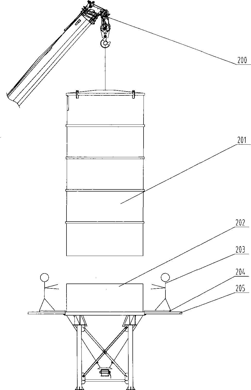
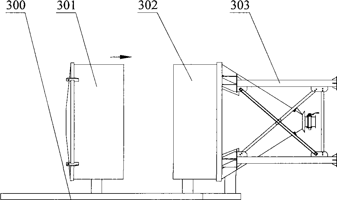
[0054] Embodiment 1 provides a kind of method of making powder tank, refer to image 3 and Figure 4 , image 3 In the method for making the powder tank provided in Example 1, the schematic diagram of the position before the top section silo and the cone section silo are docked, Figure 4 It is a schematic diagram of the position of the top section silo and the cone section silo in the first embodiment.

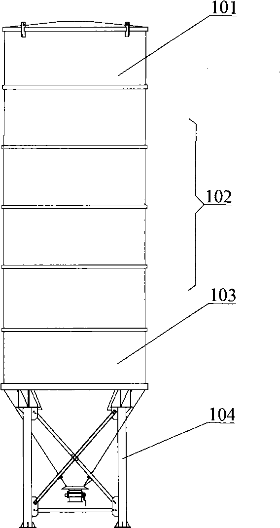
[0055] In the first embodiment, the manufactured powder tank includes a top section silo 301 and a cone section silo 302, the top section silo 301 and the cone section silo 302 are both circular in cross section, and the cone section silo 302 is fixed to the bracket 303 . Such as image 3 As shown, before welding the top section silo 301 and the cone section silo 302, the cone section silo 302 and the bracket 304 are fixed together on the platform 300, and the cone section silo 302 is placed horizontally so that its center line is in line with the horizontal plane Parall...


PUM


Abstract

The invention discloses a method for manufacturing powder tank which is used for storing powder material and comprises a first silo and a second and a second silo. The method comprises: welding the mouth between the first silo and the second silo to constitute a powder tank; the first silo and the second silo are horizontally placed when welding, thereby, the outer platform and inner platform are not needed to construct, other assistant mechanism is neither needed, the outer mouth of powder tank can be welded at proper platform; inner mouth can be welded based on inner wall of powder tank. Process of manufacturing powder tank is largely simplified because the platform is not needed to construct and detach, thereby avoiding safety accident due to platform defect.

Description

technical field [0001] The invention relates to a method for making equipment, in particular to a method for making a powder tank. Background technique [0002] The powder tank is a commonly used equipment in concrete mixing plants or other construction sites, and is used to store powder materials such as cement, admixtures, and dry powder additives. [0003] Please refer to figure 1 , figure 1 It is a schematic diagram of the structure of the powder tank. The powder tank is generally composed of multi-section silos, including the top section silo 101, the middle section silo 102 and the cone section silo 103; On the top of the silo 103, the top section silo 101 is fixed on the top of the middle section silo 102 at the upper end, and each silo is sealed and fixed by welding, so that a space for storing powdery materials is formed inside the silo. In concrete mixing plants or other construction sites, powder tanks are usually placed on corresponding supports, such as fig...

Claims


Application Information

Patent Timeline
IPC IPC(8): B65D88/06B65D90/08
Inventor 张爽蒋志辉周定明杨建辉
Owner SANY HEAVY IND CO LTD (CN)
Features
  • R&D
  • Intellectual Property
  • Life Sciences
  • Materials
  • Tech Scout
  • Unparalleled Data Quality
  • Higher Quality Content
  • 60% Fewer Hallucinations
Learn More