Micro oil pulverized coal burner

A pulverized coal burner and micro-oil technology, which is applied to burners, burners burning powder fuel, combustion types, etc., can solve the problem of inability to control the distribution of pulverized coal concentration, prevent the flame from scouring the wall surface and overheat, and is conducive to The effect of ignition and easy operation

Active Publication Date: 2009-09-30
EASTERN BOILER CONTROL CO LTD +1
View PDF9 Cites 15 Cited by
  • Summary
  • Abstract
  • Description
  • Claims
  • Application Information

AI Technical Summary

Problems solved by technology

[0005] The purpose of the present invention is to provide a micro-oil pulverized coal burner to solve the problem t

Method used


Image

  • Micro oil pulverized coal burner
  • Micro oil pulverized coal burner

Examples


Embodiment 1

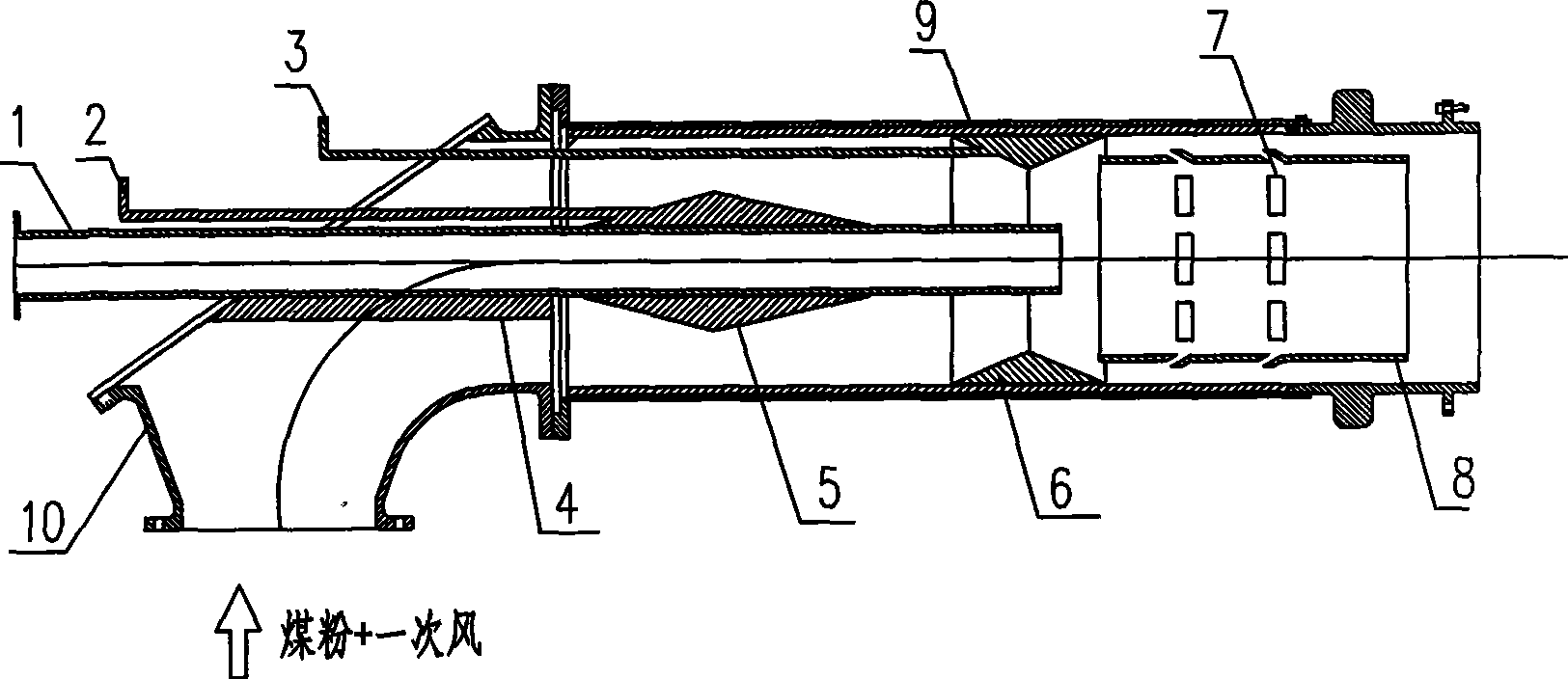
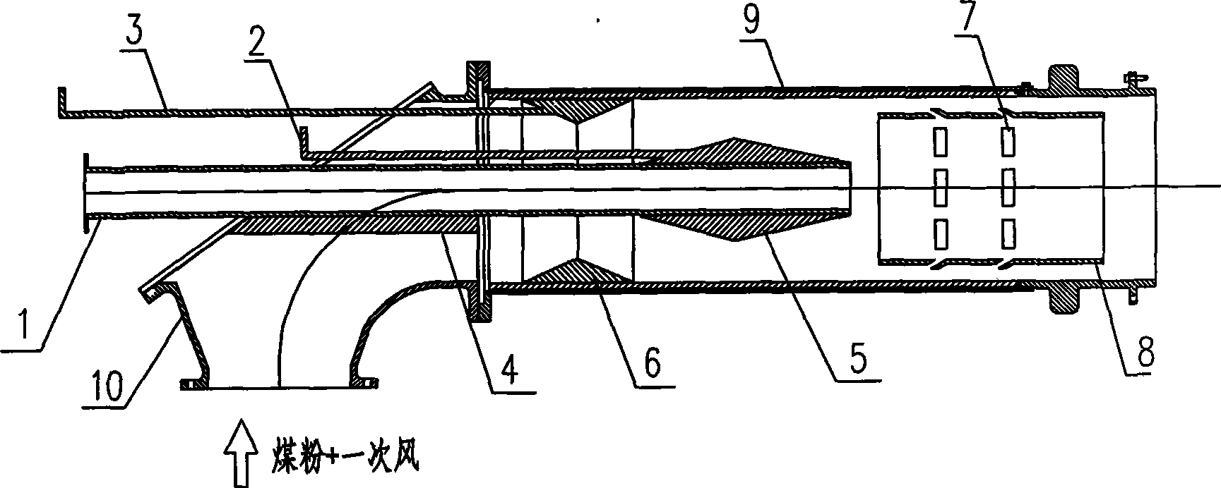
[0015] Example 1, as figure 1 , 2 As shown, a micro-oil pulverized coal burner includes an elbow 10 with a coal powder inlet and a primary air duct 9 connected thereto. At least one telescopically movable concentrator 5 is arranged on the outer wall of the micro oil gun 1 , and at least one telescopically movable guide ring 6 is arranged on the inner wall of the primary air duct 9 .

[0016] The structure of the telescopically movable concentrate 5 is such that the concentrate is connected to the inner pull rod 2, which can be pushed or pulled out manually or automatically by an actuator. The deflector ring 6 that can move telescopically is constructed such that the deflector ring is connected to the outer pull rod 3, and is pushed or pulled out manually or automatically by an actuator.

[0017] The cross-sectional shapes of the concentrated body 5 and the guide ring 6 are triangular, trapezoidal or streamline.

Embodiment 2

[0018] Embodiment 2, a kind of micro-oil pulverized coal burner, in order to ensure that the air-powder mixture outside the center cylinder 9 can enter the center cylinder, and the inner wall is cooled, the wall surface of the center cylinder is protected, and the phenomenon of high temperature burning loss is prevented from occurring. An air film tuyere 7 is also opened on the top. The rest are the same as in Example 1.

Embodiment 3

[0019] Embodiment 3, a micro-oil pulverized coal burner, in order to reduce the erosion and erosion of the micro-oil oil gun by the coal powder, a wear-resistant plate is also provided at the lower part of the micro-oil oil gun in the elbow.

[0020] The working principle of the present invention: as figure 1 As shown, when in the light oil ignition mode, manual or actuator action pushes the pull rod connecting the deflector ring, so that the deflector ring is located at the front end of the primary air duct. Manual or actuator action pulls the rod connecting the concentrate, so that the concentrate retreats to the rear of the oil barrel. The concentrated pulverized coal is led into the central guide cylinder and gathered around the outlet of the oil gun combustion cylinder, so that the high-concentration air-powder mixture is conducive to being ignited by the oil gun flame. When used as the main burner, that is, under normal operation of the boiler, such as figure 2 As sho...


PUM


Abstract

The invention provides a micro oil pulverized coal burner, which comprises an elbow joint provided with a pulverized coal inlet and a primary air pipe connected with the elbow joint, wherein the center of the primary air pipe is provided with a micro oil doper and a central cylinder in turn; the outer wall of the micro oil doper is provided with at least one condensation body which can telescopically move; the inner wall of the primary air pipe is provided with at least one guide ring which can telescopically move; the central cylinder is also provided with an air film wind opening; and the structures of the condensation body and the guide ring which can telescopically move are that: the condensation body is connected with an inner pull rod, the guide ring is connected with an outer pull rod, and the inner and the outer rods can be pushed in or pulled out manually or automatically pushed in or pulled out by an actuator. Because the outer wall of the micro oil doper is provided with at least one condensation body which can telescopically move, and the inner wall of the primary air pipe is provided with at least one guide ring which can telescopically move, the internal structure of the burner can be changed according to operating conditions; under the states of micro oil ignition and normal combustion, different concentration distribution requirements of the pulverized coal are met; and the micro oil pulverized coal burner is used for the oil saving ignition start and the low-load stable combustion in pulverized coal fired boilers in large-sized power stations.

Description

technical field [0001] The invention relates to a pulverized coal burner, in particular to a micro-oil pulverized coal burner. It can be used for fuel-saving ignition and low-load stable combustion of large-scale power plant pulverized coal boilers, and can also be used for burners in normal operation of power plant units. Background technique [0002] The micro-oil ignition system is a very effective and practical pulverized coal boiler ignition and stable combustion fuel-saving technology that has emerged in my country in recent years. The fuel-saving effect of this technology can reach more than 90%, and it has the outstanding advantages of less initial investment, wide adaptability of coal types, simple system, convenient operation and less maintenance workload. The use of this fuel-saving ignition technology can greatly reduce the ignition and fuel consumption of coal-fired thermal power plants, reduce power generation costs, and create huge economic and social benefit...

Claims


Application Information

Patent Timeline
IPC IPC(8): F23D1/00
Inventor 刘泰生李庚钟斌刘彦涛马德龙
Owner EASTERN BOILER CONTROL CO LTD
Why Eureka
Try Eureka