

Action surplus of robot calculation display method and device
A computing display, richness technology, used in electrical program control, recording and playback systems and other directions
- Summary
- Abstract
- Description
- Claims
- Application Information
AI Technical Summary
Problems solved by technology
Method used
Image

Examples
no. 1 Embodiment approach
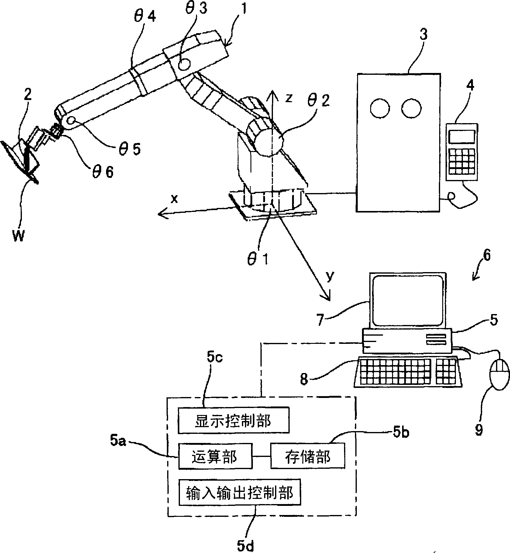
[0048] In this embodiment, if figure 1 As shown, an example of a welding robot 1 for welding a joint portion to which the present invention is applied is shown for a workpiece W made of a thick plate. A welding robot (hereinafter simply referred to as "robot") 1 holds a welding torch 2 as a processing tool at its tip. The robot 1 in this embodiment is a 6-axis articulated robot having common rotary joints θ1 to θ6 as an industrial robot, but the present invention can also be applied to other types of robots described in detail later.
[0049] The robot 1 is controlled by a control device 3 equipped with a computer. The control device 3 controls the robot 1 according to a program (teaching program) in which motion has been taught in advance. The operating conditions (including welding current, etc.) of the welding torch 2 can also be controlled by the control device 3 according to the teaching program, and a dedicated control device (not shown) for the welding torch 2 can als...
no. 2 Embodiment approach
[0073] In the calculation of the operating margin in the procedure 2, upper and lower limit values when a plurality of components are changed may be calculated. refer to Figure 9 For example, when looking for the combination of the xte component and the yte component of the drawing, since the area B surrounding the upper and lower limit values of the xte component and the yte component respectively is an actionable area, the operation can be shortened by finding a part outside this range time. In addition, if only the trend is simply known, it is sufficient to be in the area B surrounding the upper and lower limit values of each component.
[0074] Figure 10 Shown is a process for finding a combination of xte components and yte components in the calculation of the operating margin. The calculations in steps S10-2 to S10-4 are repeated for each teaching point and each target point (steps S10-1, S10-5). In addition, the calculation result is stored for later display ...
no. 3 Embodiment approach
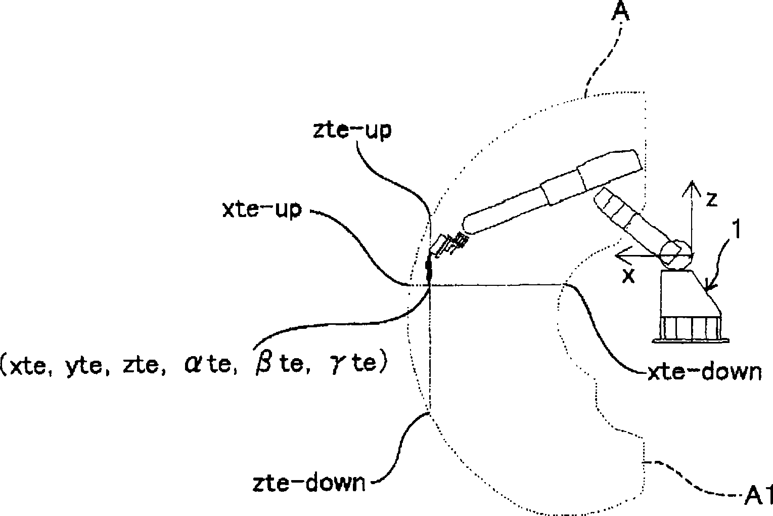
[0079] In the first embodiment, the motion margin (the upper and lower limits of each component) is calculated for the direction of the reference coordinate system of the robot 1 , but the motion margin may be calculated for an arbitrarily set standard coordinate system. By setting the standard coordinate system so that the coordinate axis coincides with the direction in which the motion margin is desired to be known, it is possible to obtain a motion margin that is easier for the operator to grasp. refer to Figure 5 For example, when performing pre-processing measurement based on contact sensing or the like on a workpiece W arranged obliquely with respect to the reference coordinate system (x, y, z, α, β, γ) of the robot 1, the robot 1 is often made Move in the direction in which the coordinate system is tilted. In this case, since the margin of action in the direction inclined relative to the reference coordinate system becomes important (the operator wants to know the all...
PUM
 Abstract
Description
Claims
Application Information