Supercharge Your Innovation With Domain-Expert AI Agents!

Portable LED device and LED system

A technology of LED devices and lighting devices, applied in the field of LED systems, can solve the problems of inconvenient carrying and unfavorable use by ordinary people

Inactive Publication Date: 2009-09-30
深圳市中庆微科技开发有限公司
View PDF0 Cites 4 Cited by
  • Summary
  • Abstract
  • Description
  • Claims
  • Application Information

AI Technical Summary

Problems solved by technology

However, at present, when many LED technical staff are doing on-site demonstrations of LED screens, because the existing LED screen demonstration devices are relatively large and inconvenient to carry, various troubles will occur when using them, which is not conducive to the use of ordinary people.

Method used


Image

  • Portable LED device and LED system
  • Portable LED device and LED system
  • Portable LED device and LED system

Examples


Embodiment 1

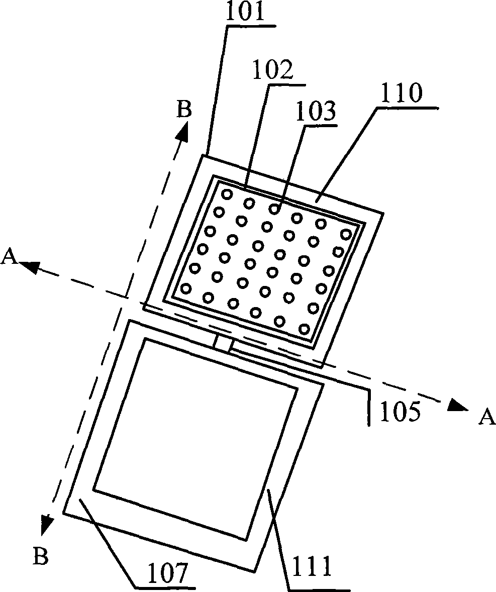
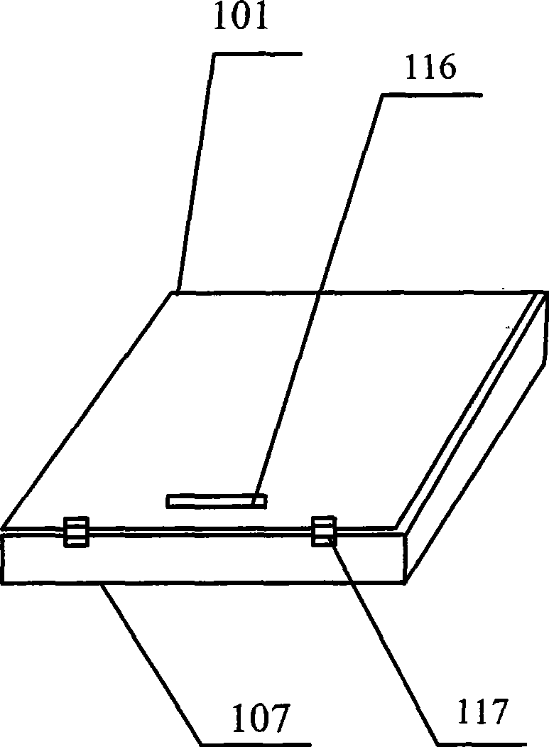
[0030] Such as figure 1 , figure 2 As shown, this embodiment provides a portable LED device, including a first device 101, a second device 107, a light emitting device 102 and a first rotating connection device 105; the first device 101 and the second device 107 are similar in shape, and the two are connected by the first rotary connection device 105 for having an open state, a partially open state, and a closed state. In the closed state, a An inner cavity, at least a part of the first device 101 is accommodated in the second device 107 .

[0031] The light emitting device 102 is fixedly arranged on at least one side of the first device 101, and includes at least one set of LED light emitting diodes 103, at least one PCB board, and at least one drive control chip and at least one Constant current drive chip; For example, a plurality of LED light-emitting diodes 103 can be evenly arranged on a large PCB board, and each LED light-emitting diode 103 is used as the main power ...

Embodiment 2

[0050] On the basis of the above examples, the LED device may also be provided with a data storage device connected to the drive control unit for storing lighting demonstration data of the light emitting device. For example, it can receive data input through the USB port.

[0051] The data storage device can also be realized by technologies such as CF card and FLASH card.

Embodiment 3

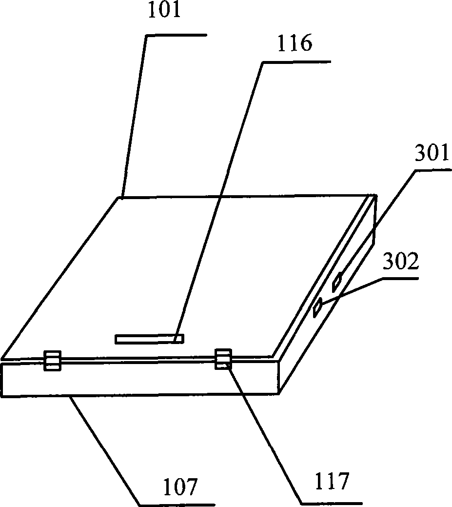
[0053] Such as image 3 As shown, on the basis of the above-mentioned examples, this embodiment provides an LED device, which is also provided with at least one power interface 302, and the power interface 302 is used to connect with the power conversion device through a wire, providing the light-emitting device and The control device provides electric energy, wherein the power interface 302 can be placed on the first device 101 or on the second device 107; the specific position of the power interface 302 can be on the left side of the first device 101 or the right side, or the left side or the right side of the second device 107, which can be set in different positions according to specific needs.

[0054] On this LED device, at least one data interface 301 is also provided. The data interface 301 is connected to the control device through wires for receiving external control signals. Wherein, the location of the data interface 301 can be on the first device 101, It can be o...


PUM


Abstract

The invention discloses a portable LED device and a portable LED system. The LED device comprises a first device, a second device, a light-emitting device, a first rotary connecting device and a control device; and the first device and the second device have similar shapes, the shell of the first device is slightly smaller than that of the second device, the first device is connected with the second device through the first rotary connecting device, and the two devices are used in opened, partial opened and closed states. In the closed state, the first device is positioned in the second device; the light-emitting device is fixedly arranged on at least one surface of the first device, and comprises a PCB board, and at least one group of LED light-emitting diodes, a drive control chip and a constant current drive chip which are arranged on the PCB board; and the control device is arranged on the first device and / or the second device. By adopting the proposal, the LED device has a simple structure, is easy to carry and convenient to fold, and is quite suitable to be used by live demonstration and ordinary workers.

Description

technical field [0001] The invention relates to an LED lighting device, in particular to a portable LED device and a portable LED system. Background technique [0002] Due to the characteristics of LED lighting, high light source, no radiation, and low power consumption, LED semiconductor light sources have been widely used in the field of lighting decoration in recent years. However, at present, when many LED technical staff are doing on-site demonstrations of LED screens, because the existing LED screen demonstration devices are relatively large and inconvenient to carry, various troubles will occur when using them, which is not conducive to the use of ordinary people. . Therefore, there are defects in the prior art and need to be improved. Contents of the invention [0003] The technical problem to be solved by the present invention is to provide a foldable LED device which is simple in structure, convenient to carry. [0004] The technical solution of the present in...

Claims


Application Information

Patent Timeline
Patent Type & Authority Applications(China)
IPC IPC(8): G09F9/33G09G3/32F21V23/00F21V23/04H05B37/02F21Y101/02F21Y115/10
Inventor 商松
Owner 深圳市中庆微科技开发有限公司
Features
  • R&D
  • Intellectual Property
  • Life Sciences
  • Materials
  • Tech Scout
  • Unparalleled Data Quality
  • Higher Quality Content
  • 60% Fewer Hallucinations
Learn More