
Wheel loader

A technology of wheel loader and rear frame, which is applied in the direction of motor vehicle, transportation and packaging, earth mover/shovel, etc. The effect of improving driving performance and simple structure

Inactive Publication Date: 2009-09-30
KOMATSU LTD
View PDF1 Cites 6 Cited by
  • Summary
  • Abstract
  • Description
  • Claims
  • Application Information

AI Technical Summary

Problems solved by technology

It is difficult to meet high-level standards such as ROPS only by strengthening the support structure of the two pillars, and it is desired to achieve a more rigid rack structure
In particular, in the rear frame of a wheel loader mainly composed of left and right main beams, the rigidity of the entire rear frame has been ensured by erecting a bottom plate between the main beams in the past, but it is difficult to improve the rigidity due to limitations. Satisfy ROPS

Method used


Image

  • Wheel loader
  • Wheel loader
  • Wheel loader

Examples


Embodiment Construction

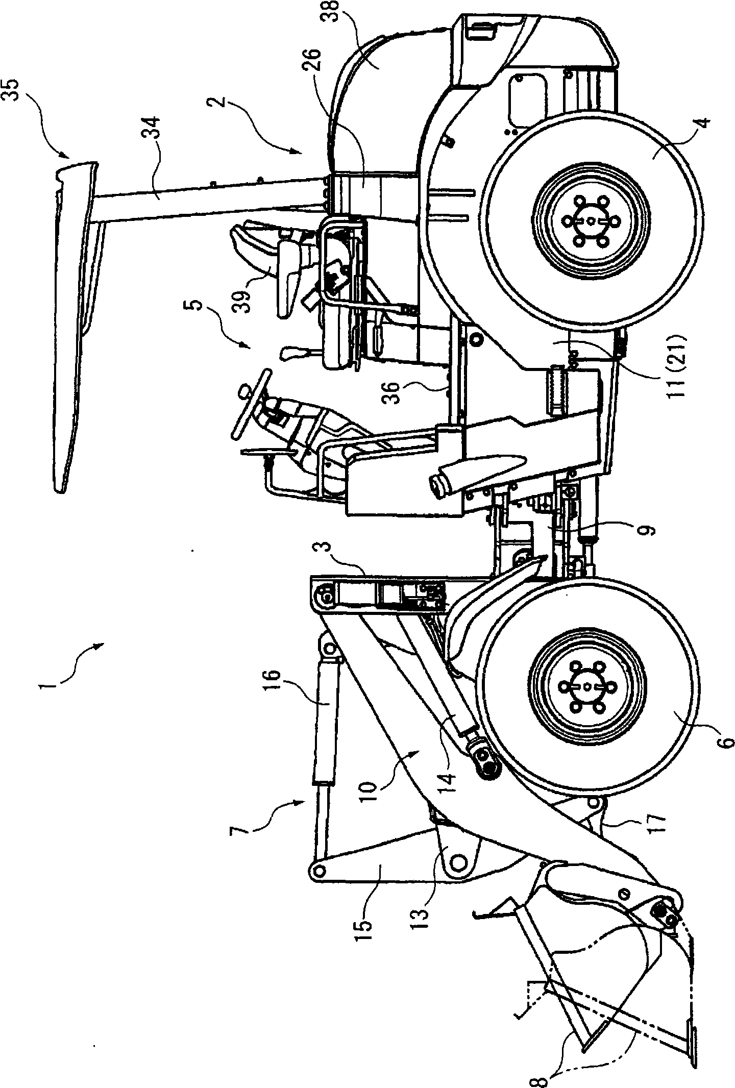
[0029] An embodiment of the present invention will be described below with reference to the drawings. figure 1 It is a side view showing the whole of the wheel loader 1 of this embodiment.

[0030] The wheel loader 1 of this embodiment has an operating weight of about 2.5 t, and is configured such that a front frame 3 is hingeably attached to the front side of a rear vehicle body 2 . The rear frame 11 of the rear vehicle body 2 is provided with rear wheels 4 and a cab 5, and accommodates an engine (not shown), a power transmission system including a hydraulic pump driven by the engine, a transmission, and the like. A seat 39 constituting the cab 5 is provided above the engine (not shown), and a roof 35 including two pillars 34 is provided behind the seat 39 . Front wheels 6 are provided on the front frame 3 , and a working device 7 is provided further forward of the front frame 3 , and a bucket 8 is attached to the front end of the working device 7 .

[0031] Among them, the...


PUM


Abstract

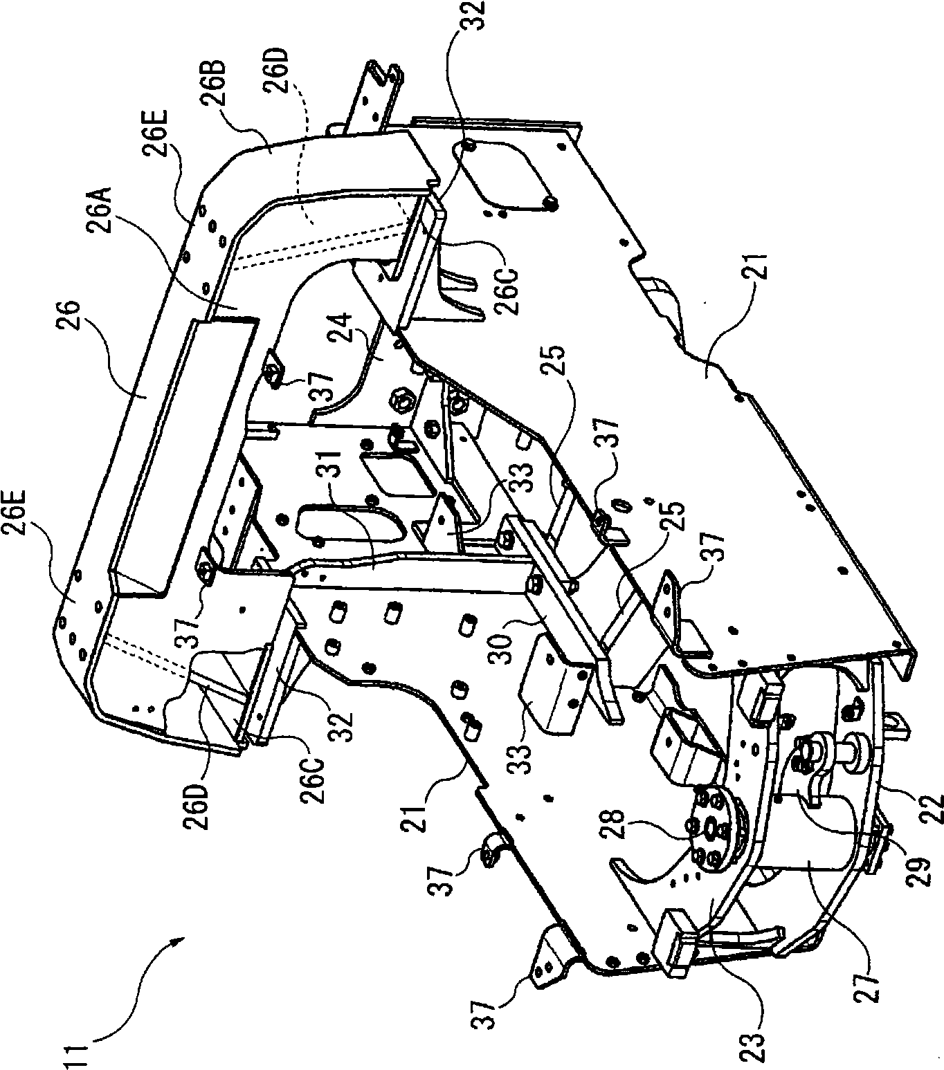
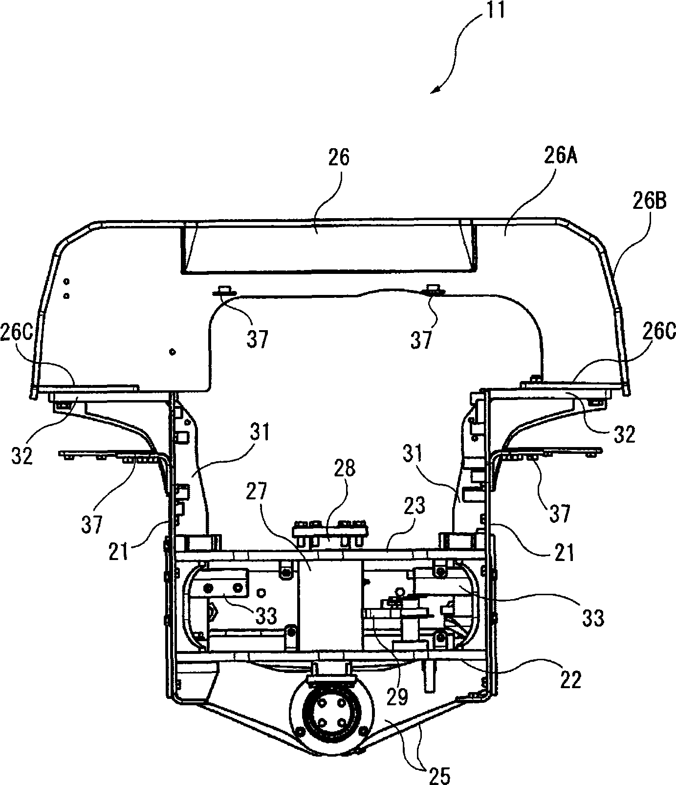
Provided is a wheel holder comprising a rear frame (11) including left and right main beams (21) formed into a plate shape. At upper side positions middle of the longitudinal direction of the rear frame (11), a reinforcing bracket (26) is spanned across the main beams (21), so that the middle position of the rear frame (11) is formed into a closed sectional structure having the reinforcing bracket (26). This closed sectional structure at the main beams (21) is specified to include an axle support (25), a reinforcing plate (30), a reinforcing rib (31) and the reinforcing bracket (26) in the recited order from the lower side to the upper side.

Description

technical field [0001] The invention relates to a wheel loader, in particular to the improvement of the rear frame structure of the rear vehicle body. Background technique [0002] Currently, in bulldozers and the like, a technique has been proposed in which two pillars support a roof covering a cab to improve forward visibility (Patent Document 1). This Patent Document 1 describes that the support body is formed into a box shape with a closed cross-sectional structure in order to increase the rigidity of the column support body. Accordingly, not only the forward visibility can be improved, but also the vibration of the support body during running can be prevented. [0003] Also in the wheel loader, the top cover with the same two-column structure as Patent Document 1 is often used. In addition, ROPS (Roll Over Protective Structure: Roll Over Protective Structure) is recommended as a safety standard in recent years. [0004] Patent Document 1: (Japanese) Utility Applicati...

Claims


Application Information

Patent Timeline
IPC IPC(8): E02F3/34B62D21/18
CPCB62D53/028E02F9/0841B62D21/186
Inventor 盐路博之荻原俊文宫根昭夫上前健志
Owner KOMATSU LTD
Learn More