Filter cleaning mechanism for air conditioning apparatus
A cleaning mechanism and filter technology, which can be used in air conditioning systems, mechanical equipment, space heating and ventilation, etc., can solve the problems of filter cleaning ability decline, dust removal, etc., and achieve the effect of increased density and easy handling
Active Publication Date: 2009-09-30
DAIKIN IND LTD
View PDF1 Cites 15 Cited by
- Summary
- Abstract
- Description
- Claims
- Application Information
AI Technical Summary
Problems solved by technology
[0005] However, it is difficult to sufficiently remove dust from the brush with the above-mentioned dust sheet, and if the uncleaned dust accumulates on the brush, the cleaning ability of the filter by the brush may be reduced.
Method used
View moreImage
Smart ImageViewing Examples
Examples
other Embodiment approach
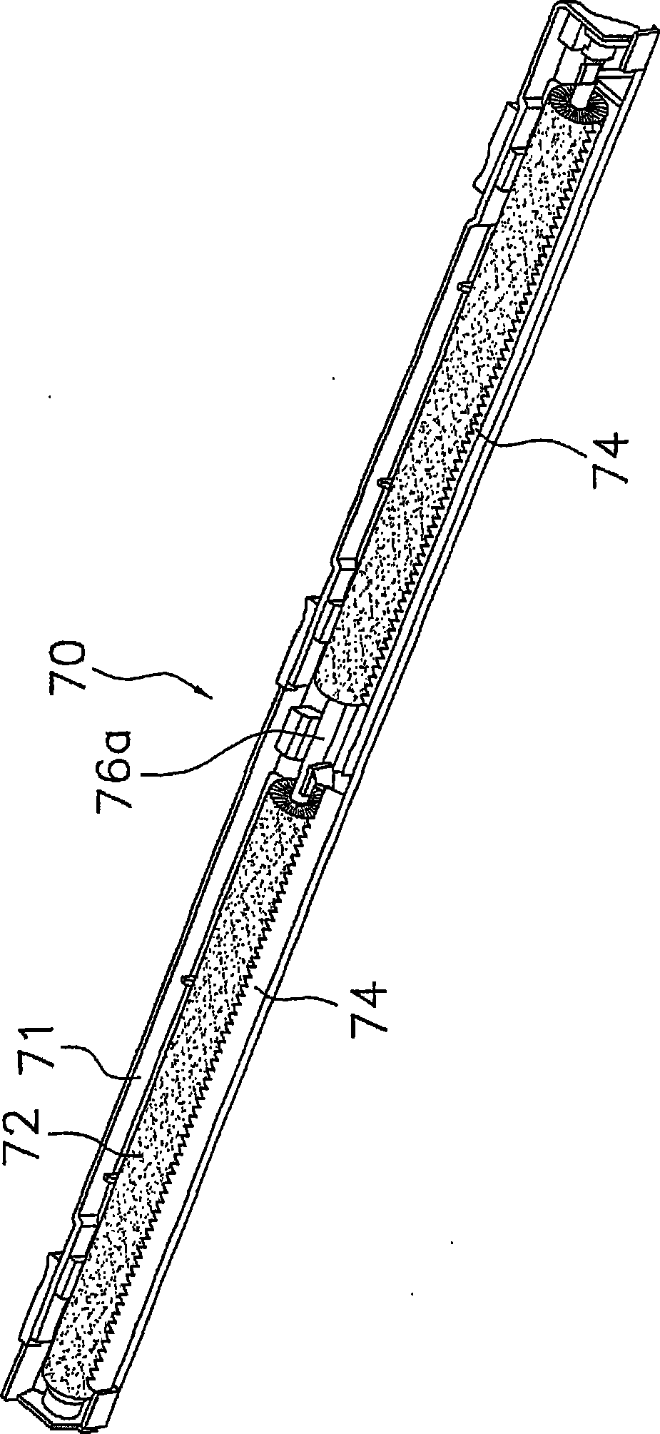
[0076] (1) In the above-mentioned embodiment, the brush cleaning part 74 is attached to the frame part 71 , but the brush cleaning part 74 may be integrated with the frame part 71 .
Login to View More PUM
 Abstract
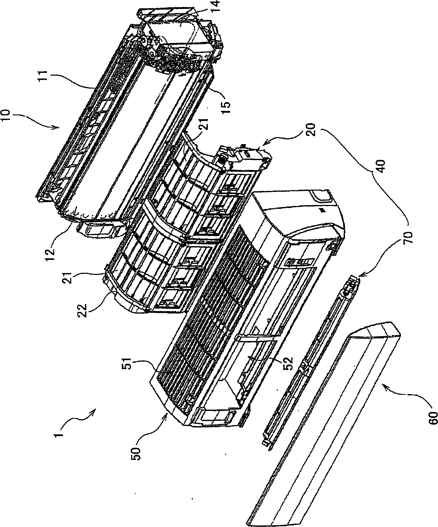
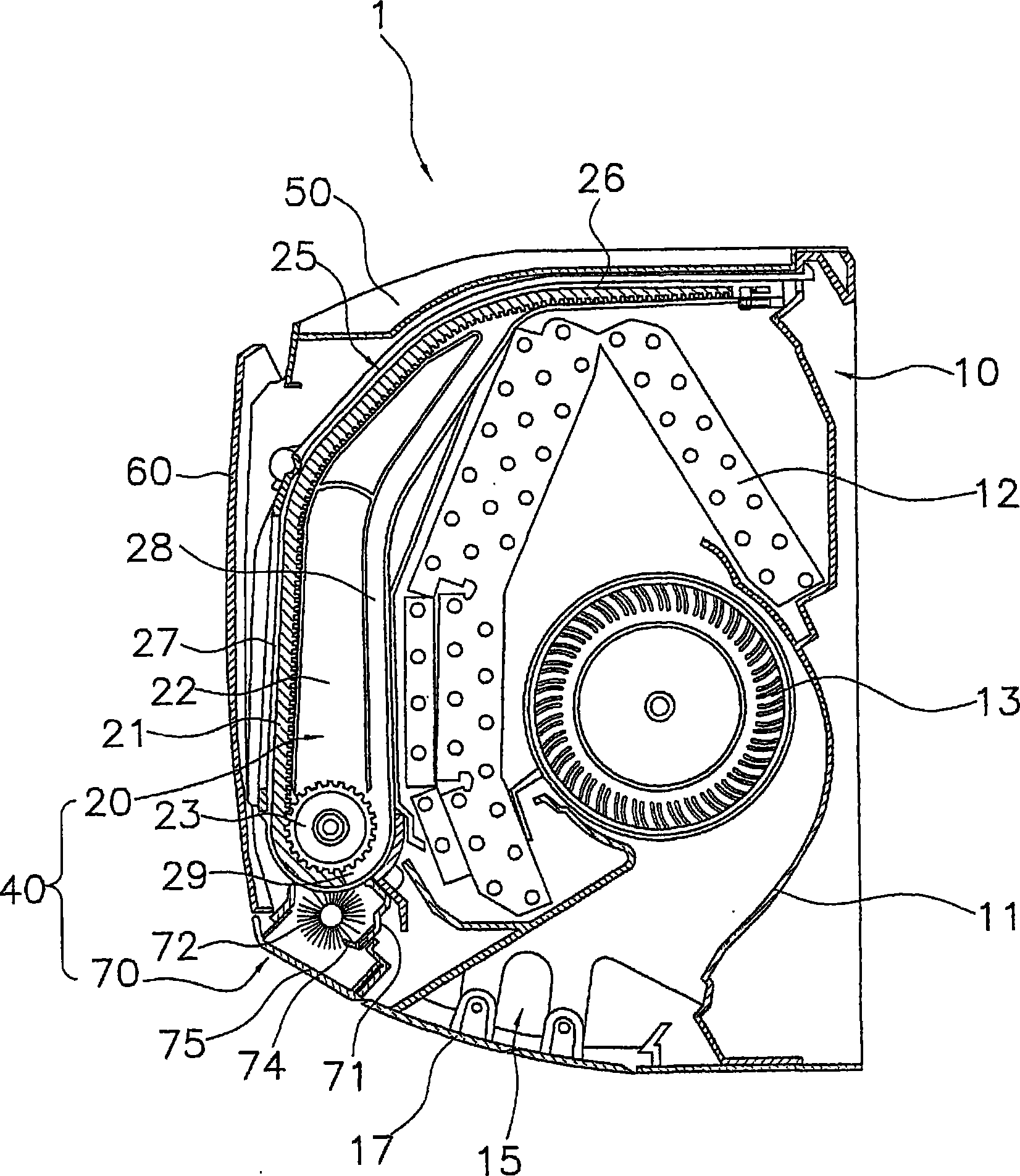
Provided are a filter cleaning mechanism by which deterioration of filter cleaning performance can be suppressed, and an air conditioning apparatus. A filter cleaning mechanism (40) for an air conditioning apparatus is provided with a filter (21) for removing dusts from air passing through, a brush section (72), a brush driving section (73), and a brush cleaning section (74). The brush section (72) is provided with a core material (76), and a plurality of wire rods (77) arranged on the circumference of the core material (76), and dusts are removed from the filter (21) by bringing the wire rods (77) into contact with the filter (21). The brush driving section (73) rotates the brush section (72). The brush cleaning section (74) is arranged along the rotating shaft direction of the brush section (72) and has a comb-like shape that makes contact with the brush section (72). The brush cleaning section scrapes out dusts from the brush section (72) by rotating the brush section (72).
Description
technical field [0001] The invention relates to a filter cleaning mechanism of an air conditioner and the air conditioner. Background technique [0002] An air conditioner is generally provided with a filter for removing dust from the air taken in from the room. However, if the dust adheres to the filter and accumulates, ventilation resistance increases. Therefore, an air conditioner having a filter cleaning mechanism that automatically cleans a filter has been proposed (see Patent Document 1). [0003] In such a filter cleaning mechanism, when the brush portion comes into contact with the filter surface, dust can be removed from the filter and the filter can be cleaned. On the other hand, the dust adhering to the brush portion is removed by being swung off from the brush portion by the dust sheet protruding so as to come into contact with the brush portion. [0004] Patent Document 1: Japanese Publication No. 62-160221 [0005] However, it is difficult to sufficiently re...
Claims
Login to View More Application Information
Patent Timeline
 IPC IPC(8): F24F13/28F24F8/90F24F8/108
CPCF24F2001/0048B01D46/0065F24F2003/1639F24F3/1603F24F1/0007F24F1/0057F24F8/90F24F8/10F24F1/0073F24F1/0063B01D46/681F24F8/108F24F13/28F24F2221/22
Inventor 中西淳一宫上正人上山正治
Owner DAIKIN IND LTD
Features
- R&D
- Intellectual Property
- Life Sciences
- Materials
- Tech Scout
- Unparalleled Data Quality
- Higher Quality Content
- 60% Fewer Hallucinations
Learn More Browse by: Latest US Patents, China's latest patents, Technical Efficacy Thesaurus, Application Domain, Technology Topic, Popular Technical Reports.
© 2025 PatSnap. All rights reserved.Legal|Privacy policy|Modern Slavery Act Transparency Statement|Sitemap|About US| Contact US: help@patsnap.com


