Eureka AIR delivers breakthrough ideas for toughest innovation challenges, trusted by R&D personnel around the world.

Straw chopping apparatus in combine harvester

A technology for combine harvesters and chopping devices, applied in the direction of harvesters, cutters, crop processors, etc., can solve problems such as waste of resources, environmental pollution, blade position changes, etc., to improve service life, facilitate popularization and application, and be good The effect of dynamic balance

Inactive Publication Date: 2009-10-07
ZHONGJI SOUTHERN MACHINERY
View PDF1 Cites 12 Cited by
  • Summary
  • Abstract
  • Description
  • Claims
  • Application Information

AI Technical Summary

Problems solved by technology

The previous combine harvesters basically did not have a straw chopping device, and straw returning to the field required manual chopping or other equipment. The straw can only be incinerated, which not only wastes a lot of resources, but also causes environmental pollution.
[0003] The straw chopping device installed on the existing harvester still has some structural defects, the blade is not rigid enough, and the blade slips and moves during the rotation process, etc.
The Chinese patent CN00251550.4 discloses a shredding device for a harvester. The moving blade adopts a single turret and a single bolt in the installation structure. This structure not only has poor rigidity, but also has no positioning on the blade circumference. , the position of the blade will change, and it is difficult to return to the original position after replacing the moving blade, which will eventually affect the dynamic balance of the entire moving knife roller

Method used


Image

  • Straw chopping apparatus in combine harvester
  • Straw chopping apparatus in combine harvester
  • Straw chopping apparatus in combine harvester

Examples


Embodiment Construction

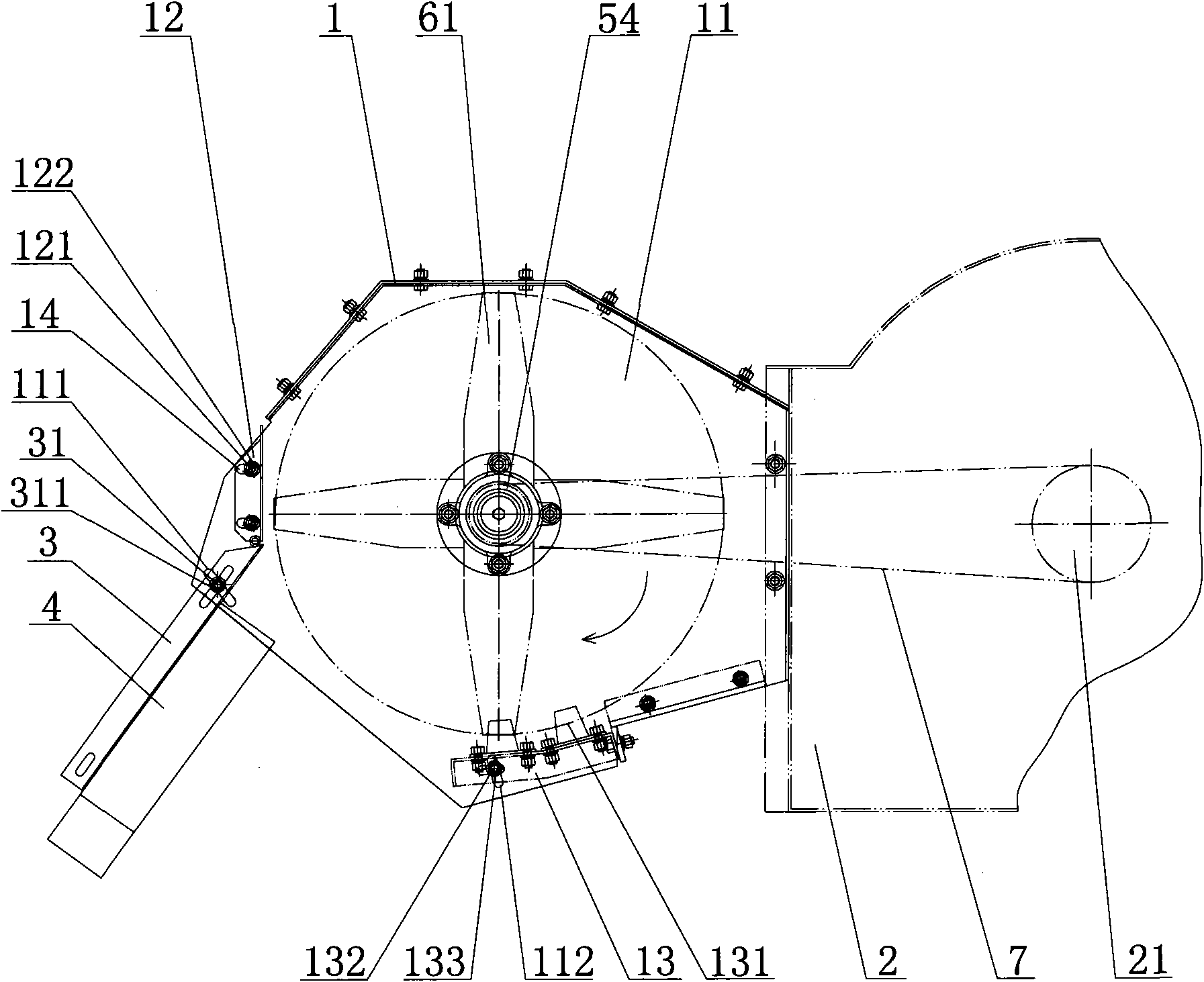
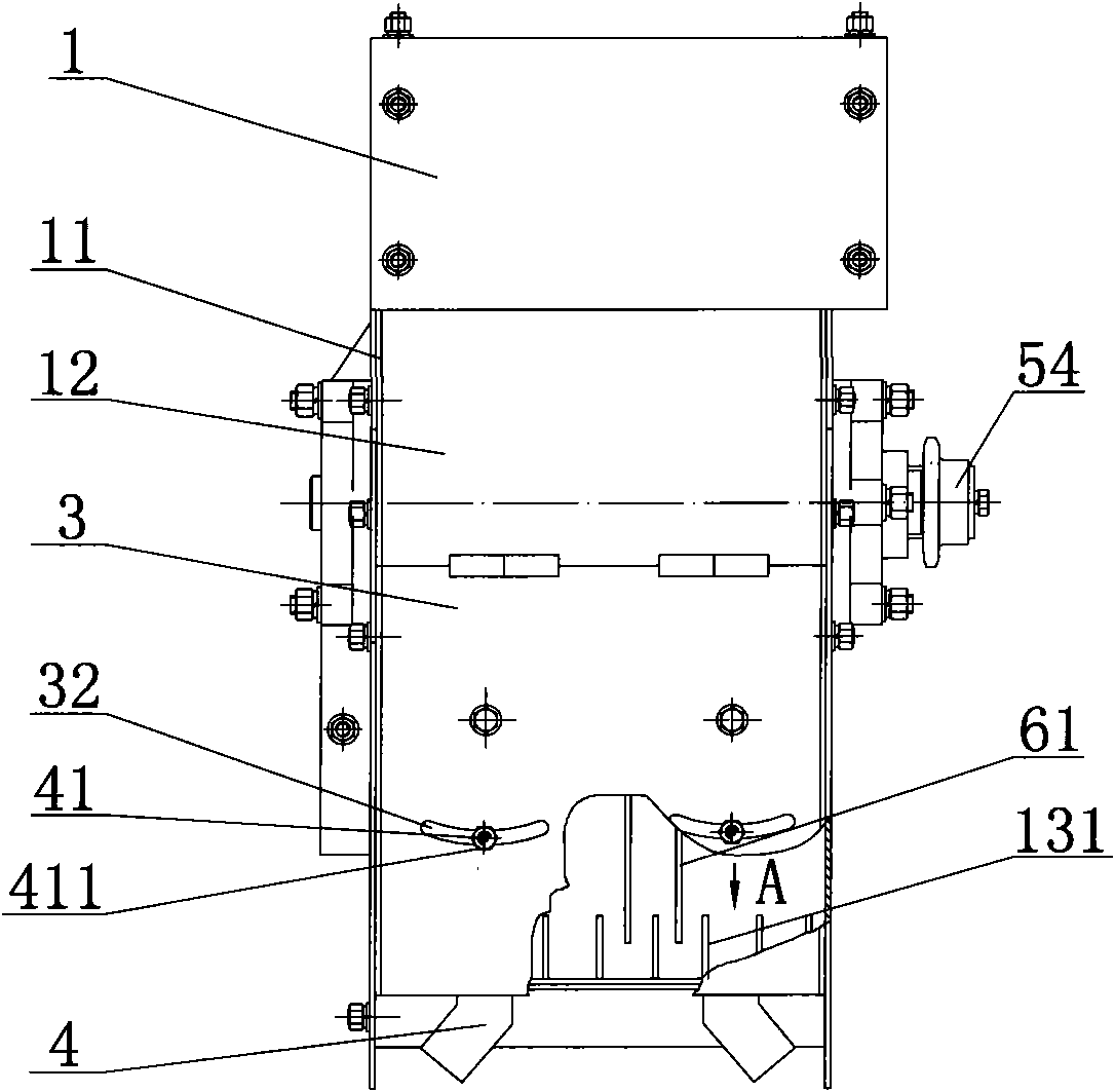
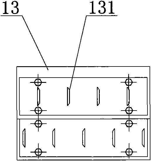
[0021] Such as figure 1 , figure 2 , image 3 As shown in the schematic diagram of the assembly structure of the present invention, a straw chopping device of a combine harvester includes a shell 1 connected to the threshing drum 2, and the left and right sides of the shell 1 are respectively provided with wall panels 11, and the shell 1 There is a rear baffle 12 at the rear end of the housing 1, and a bottom plate 13 is installed at the bottom of the housing 1. A knife-roller mechanism is installed transversely between the wallboards 11 of the housing 1, and a plurality of moving knife mechanisms are installed annularly along the axial direction of the knife-roller mechanism. The movable knife roller mechanism is provided with two movable blades 61 installed side by side, the bottom plate 13 is provided with fixed blades 131 interlaced with the positions of the movable blades 61, and the side of the wallboard 11 corresponding to the installation position of the bottom plate...


PUM


Abstract

The invention discloses a straw chopping apparatus in combine harvester, which comprises a casing; wallboards are disposed respectively on the left and right side of the casing; a backboard is disposed on the back of the casing; a bottom board is disposed on the bottom of the casing; a roller mechanism is transversely mounted between the wallboards of the casing by passing through; a plurality of movable cutter mechanisms are installed along the axial direction of the roller mechanism; two movable blades are mounted in parallel on each movable cutter mechanism; fixed blades with rests are disposed on the bottom board interleaved with the movable blades; the movable blades and rest in each group is integrated by connected in series by at least two fastening mechanisms; blade protectors for improving the strength and rigidity of the movable blades are disposed on the connection points between the movable blades and rests; spacing sheets are disposed between the rests to keep fixed space between the movable blades; Thus, the rest positions and the original balance can be kept even the movable blades are replaced. Matched with combine harvester, the invention has the functions of harvesting, arranging grass, cutting grass and broadcasting the broken grass on the land after harvesting.

Description

technical field [0001] The invention relates to the field of agricultural machinery, in particular to a straw chopping device of a combine harvester. Background technique [0002] Straw is the stem and leaf of a crop. In the traditional process, after harvesting the grain, the remaining straw is burned as energy or waste. At present, the National Ministry of Agriculture promotes straw returning to the field to replace previous straw burning. In this way, the land is fertilized, environmental pollution is reduced, and the occurrence of some fires can also be reduced to a certain extent. The previous combine harvesters basically did not have a straw chopping device, and straw returning to the field required manual chopping or other equipment. The straw can only be incinerated, which not only wastes a lot of resources, but also causes environmental pollution. [0003] The straw chopping device installed on the existing harvester still has certain defects in structure, the bla...

Claims


Application Information

Patent Timeline
Patent Type & Authority Applications(China)
IPC IPC(8): A01D41/12A01D69/06A01D82/00A01F12/40
Inventor 曾联黄江军杨锦章
Owner ZHONGJI SOUTHERN MACHINERY
Why Eureka
Eureka Blog
Learn More