Cross runout device of grass cutter

A lawn mower and horizontal positioning technology, which is applied in the direction of lawn mowers, harvesters, cutters, etc., can solve the problems of low cutting efficiency, low power of lawn mowers, and limited use range, so as to improve operating efficiency , flexible operation and increased mobility

Active Publication Date: 2009-10-07
常州汉森机械股份有限公司
View PDF0 Cites 3 Cited by
  • Summary
  • Abstract
  • Description
  • Claims
  • Application Information

AI Technical Summary

Problems solved by technology

But this kind of lawn mower is a fixed structure through the three-point suspension position, the working width position of the lawn mower cannot be adjusted during the operation process, the working width of the lawn mower is fixed, and the working area can only be some wide tractor travel. area, the scope of work is relatively fixed
In addition, the cutter shaft of the mower is usually set horizontally or vertically. When the mower is connected to the tractor, the mower cannot be tilted. Therefore, the mower cannot work on special terrain such as ditches, bank slopes, and tree walls. The scope of use is limited
Another type of lawn mower is based on its own motor or directly driven manually, but this type of lawn mower can be controlled by manpower to operate on special terrains such as small plots, ditches, embankment slopes, and tree walls. However, the power of the lawn mower is small, and the cutting efficiency is very low, so it can only be used for the trimming of small garden lawns.

Method used


Image

  • Cross runout device of grass cutter
  • Cross runout device of grass cutter
  • Cross runout device of grass cutter

Examples


Embodiment Construction

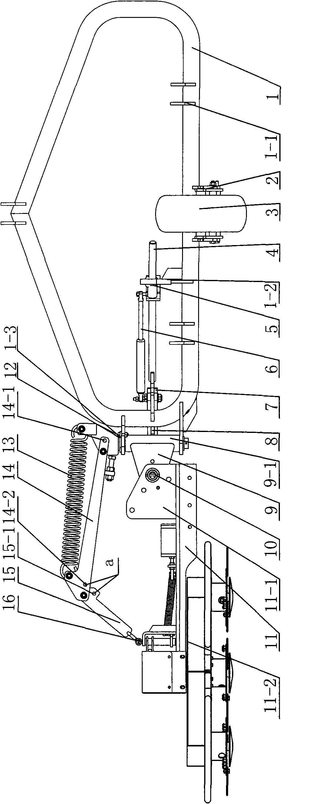
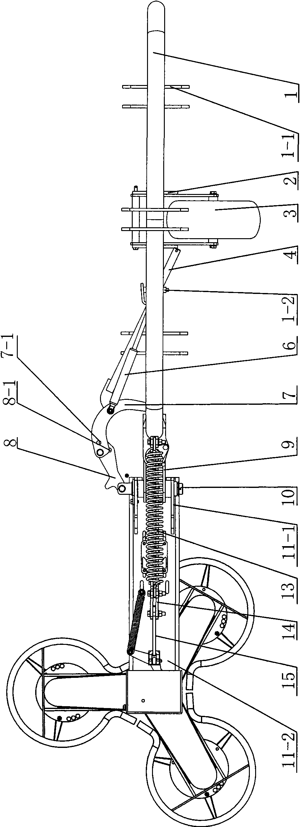
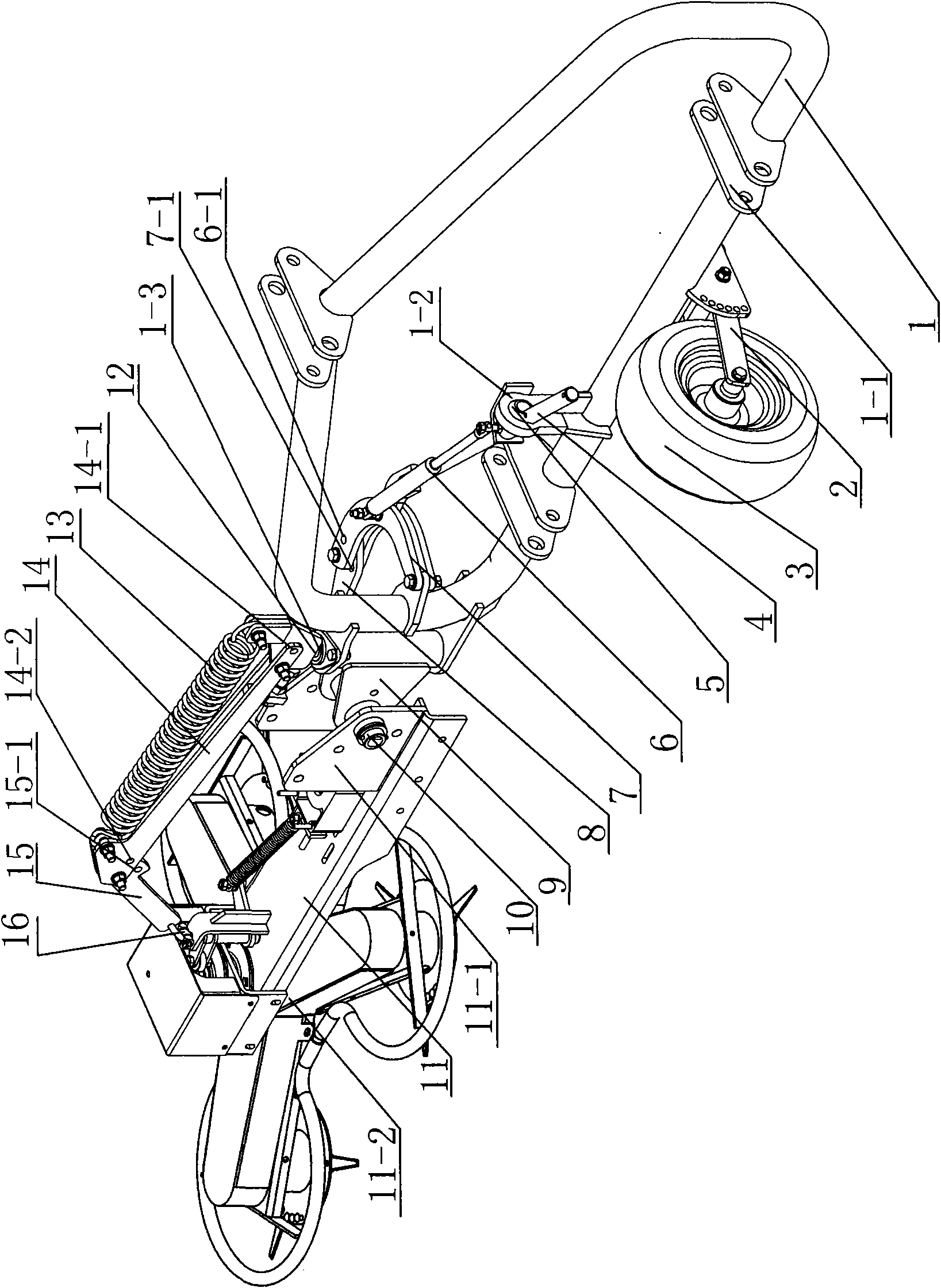
[0011] see Figure 1~3 As shown, the horizontal deflection device of the lawn mower of the present invention includes a body 11, a vertical shaft 12, a support 9, a swing mechanism, a deflection mechanism, and a suspension frame 1. The body 11 is provided on the side opposite to the blade holder 11-2 Connecting seat 11-1. Suspension frame 1 is provided with upper and lower suspension seats 1-1, which form a three-point connection with the tractor. Suspension frame 1 is placed horizontally on the side of the tractor. The suspension frame 1 of the present invention has a closed ring structure and is suspended The front fork 2 is also installed at the bottom of the frame 1, the walking wheel 3 is installed on the front fork 2, and the standpipe 1-3 is fixed on one side of the suspension frame 1, and the vertical shaft 12 is vertically installed in the standpipe 1-3 holes. The rotating sleeve 9-1 of 9 is sleeved on the riser 1-3. Both the vertical shaft 12 and the rotating sleeve 9-1 c...


PUM


Abstract

The invention relates to a cross runout device of a grass cutter, wherein one side of a suspension bracket is fixed with a vertical pipe; a vertical shaft and the teleflex of a support saddle are vertically installed on the vertical pipe; a connecting seat of the machine body is hinged on the support saddle through a lateral pin; a swing mechanism comprises a first connecting rod, a guide bar and a horizontal driving piece; two ends of the first connecting rod which is positioned outside the support saddle are respectively hinged on the lateral pin and the suspension bracket; the guide bar and one end of the horizontal driving piece are hinged on the first connecting rod; the other end of the horizontal driving piece is connected with the guide bar; the guide bar is connected with the suspension bracket through a spherical joint; a deflection mechanism comprises a front connecting rod of the machine body, a back connecting rod of the machine body, and a deflection driving piece; the front connecting rod of the machine body and the back connecting rod of the machine body which are hinged are respectively hinged on the machine body and the vertical shaft; and the deflection driving piece arranged at the upper part of the back connecting rod of the machine body is respectively connected with the back connecting rod of the machine body and the vertical shaft. Under the situation that a tractor is fixed by trifilar suspension, the cross runout device can conveniently change the working width of the grass cutter, lead the grass cutter to deflect and tilt, and realize multiaspect cutting operation.

Description

Technical field [0001] The invention relates to a horizontal deflection device of a lawn mower, belonging to the technical field of lawn mowers for agricultural and forestry machinery. Background technique [0002] Lawn mowers are powered by machinery and are mainly used for agricultural and gardening operations. Lawn mowers of this type of structure are mounted directly behind the tractor and are usually used for pruning large areas of vegetation. However, this kind of lawn mower is a fixed structure through the three-point suspension position. The working width of the lawn mower cannot be adjusted during the operation. The working width of the lawn mower is fixed, and the working area can only be widened by the tractor. The scope of operation is relatively fixed. In addition, the cutter shaft of the lawnmower is usually set horizontally or vertically. When the lawnmower is connected to the tractor, the lawnmower cannot be tilted. Therefore, the lawnmower cannot operate on speci...

Claims


Application Information

Patent Timeline
Patent Type & Authority Applications(China)
IPC IPC(8): A01D67/00A01D34/835A01D101/00
Inventor 钟世启顾国平孙旭亮陈冬平
Owner 常州汉森机械股份有限公司
Why Eureka
Try Eureka