Node of connection of column and beam

A node and connection technology, applied in the field of the connection between columns and beams, can solve the problems of increasing the weight and stiffness of the structure, reducing the effective usable area, increasing the cost of the building, etc., so as to improve the resistance to damage and protect people's lives. Property safety, the effect of improving ductility

Inactive Publication Date: 2009-10-07
SOUTH CHINA UNIV OF TECH
View PDF0 Cites 8 Cited by
  • Summary
  • Abstract
  • Description
  • Claims
  • Application Information

AI Technical Summary

Problems solved by technology

According to the research results of relevant experts and scholars, the rigidity of the floor slab is very large, the beams and slabs are equipped with steel bars, and the bending resistance of the floor slab is also very large. The building structure design carried out according to the relevant structural design codes of our country has not actually reached The results of "strong columns and weak beams" required by the code have great potential safety hazards
The survey results of the Wenchuan Earthquake showed that, under the action of the earthquake, the structure with frame components is mainly damaged at the end of the column, while the end of the beam is rarely damaged. A large number of buildings collapsed due to the damage of the column, causing huge lives. Property loss, the building did not really realize "strong columns and weak beams", which did not meet the requirements of the code
Once the column end is damaged, it is often impossible to repair. Therefore, to realize "strong column and weak beam" with the current structural form, it is bound to greatly increase the cross-sectional size of the column and the amount of reinforcement, but at the same time it brings the following problems: (1) Greatly increase the cost of the building; (2) affect the use of the building and reduce the effective use area; (3) increase the weight and rigidity of the structure, and further increase the earthquake effect, and quite a few columns even become short columns, further increasing the building cost

Method used


Image

  • Node of connection of column and beam
  • Node of connection of column and beam
  • Node of connection of column and beam

Examples


Embodiment 1

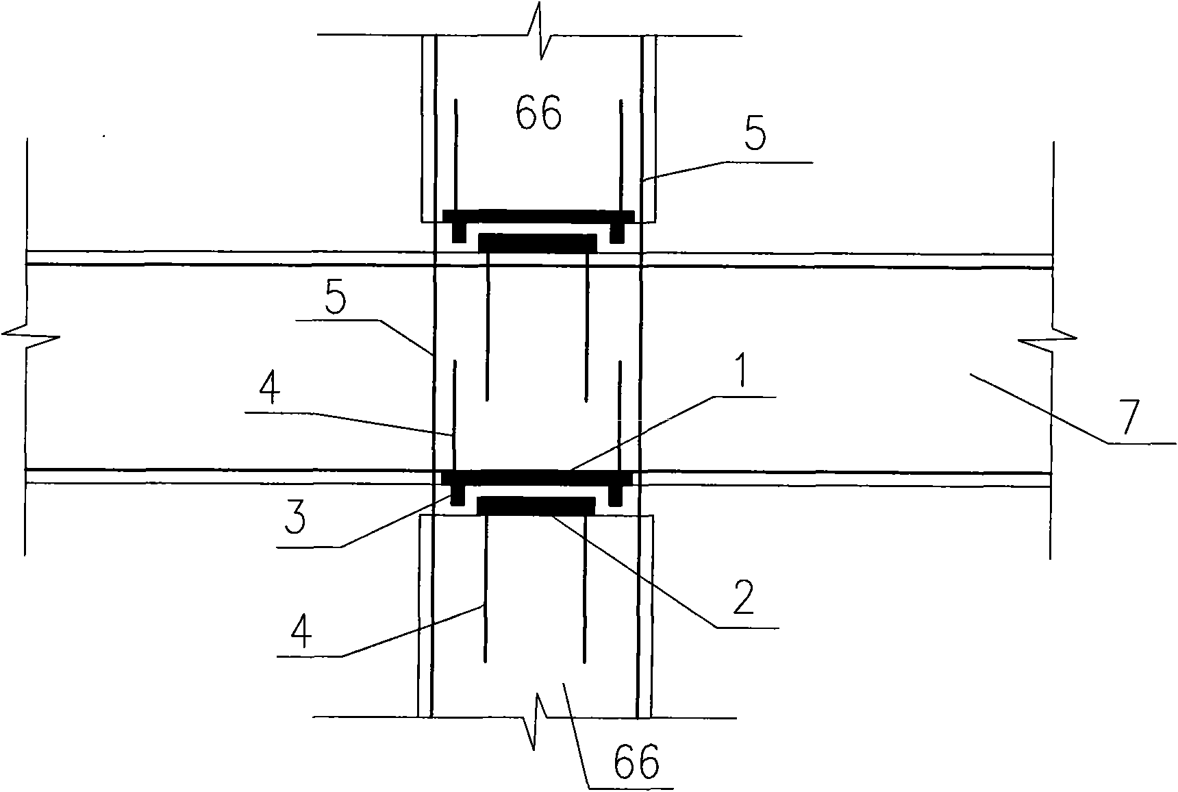
[0026] like figure 1 , figure 2 , image 3 As shown, the present invention is applied to reinforced concrete frame structures. The joint is composed of steel plate 1, steel plate 2 and column reinforcement 5. At the joint between column end 66 and beam plate 7 of the building, two steel plates are placed up and down: steel plate 1 and steel plate 2. The contact area of ​​steel plate 1 and steel plate 2 is smaller than that of the column The cross-sectional area of ​​the end 66 increases the rotation capacity and energy dissipation capacity of the joint. Both the steel plate 1 and the steel plate 2 are fixed with a number of short steel bars 4, and the short steel bars 4 are fixed in the concrete of the column end 66 or the beam plate 7, and the column bars 5 are in two The number of configurations in the steel plate range is less than that of other parts of the column end 66, so that the stiffness and bending resistance of this node are lower than the stiffness and bending ...

Embodiment 2

[0029] like Figure 4 , Figure 5 As shown, the present invention is applied to a frame structure provided with diagonal stay rods 8 . The present invention can form a truss-type lateral force-resisting system in conjunction with a frame of diagonal tie rods 8. The two ends of the tie rods 8 are respectively fixed on the beam-column joints 9 of the upper and lower floors. The tie rods 8 can be made of high-strength steel strands or high-strength steel bars. The shear force and bending moment of the column 6 are greatly reduced, and the column 6 mainly bears the axial force, giving full play to the advantages of high compressive strength of the concrete, and improving the bearing capacity of the column 6. Therefore, under the action of an earthquake, the column end 66 will not be damaged, thereby achieving the effect of "strong column and weak beam" required by the code, and greatly improving the seismic performance of the building.

Embodiment 3

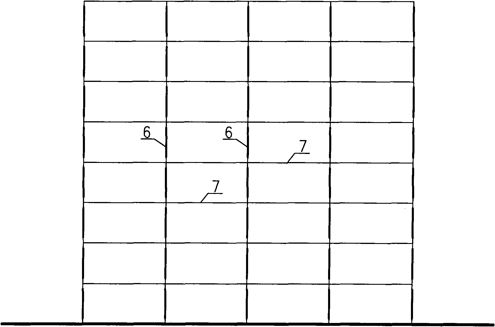
[0031] like Image 6 As shown, the present invention is applied to a frame-shear wall structure or a frame-tube structure. Diagonal tie rods 8 can be set in the frame, such as Figure 7 As shown, the two ends of the tie rods 8 are respectively fixed on the beam-column nodes 9 on the upper and lower floors, and can also be anchored at the intersection of the beam plate 7 and the shear wall 10. The tie rods 8 can be made of high-strength steel strands or high-strength steel bars, The hybrid frame and the shear wall 10 form a hybrid lateral force-resistant system, which is suitable for high-rise and super high-rise building structures designed for earthquake resistance.


PUM


Abstract

The invention discloses a novel column end node of a building structure, namely a column is connected with a floor slab by arranging two steel plates. The contact area of the two steel plates is smaller than the section area of a column end; the configured quantity of vertical steel bars of the column between the two steel plates is relatively less than that of the column end; the rigidity of the node and the bending resistance are lower than that of other parts of the column end; a control node area is an energy consumption area of the column, the column end is avoided from generating damage under the action of horizontal loading of earthquake or wind and the like and the safety of the whole column is protected, thus achieving the effect of strong column and weak beam of code requirements, improving the damage resistance of the building under the action of loading of earthquake and wind, and effectively protecting the safety of lives and property of people.

Description

technical field [0001] The invention relates to a joint of a reinforced concrete structure and a steel-concrete composite structure applied to construction engineering, in particular to a joint connecting a column and a beam. Background technique [0002] In the current reinforced concrete structure or steel-concrete composite structure, the structural systems include frame structure, shear wall structure, frame-shear wall structure, frame-tube structure, tube structure, and tube-in-tube structure. The interconnection of each component of the above-mentioned various structures adopts rigid connection. In general multi-storey and high-rise buildings, frame structures, frame-shear wall structures, and frame-tube structures are widely used due to their flexible layout and large space. [0003] The column and the floor of the conventional structure are rigidly connected. Under the action of load, the maximum bending moment of the column is located at the column end, and the col...

Claims


Application Information

Patent Timeline
Patent Type & Authority Applications(China)
IPC IPC(8): E04B1/38
Inventor 陆观宏王湛
Owner SOUTH CHINA UNIV OF TECH
Why Eureka
Try Eureka