Venetian blinds with magnetic controller for regulation

A shutter, adjustable technology, applied in the direction of windows/doors, door/window protection devices, shading screens, etc., can solve the problems of expensive, moving shutters, unable to realize shutters from top to bottom, etc.

Inactive Publication Date: 2009-10-07
彭哲彦 +1
View PDF0 Cites 8 Cited by
  • Summary
  • Abstract
  • Description
  • Claims
  • Application Information

AI Technical Summary

Problems solved by technology

[0002] The problems that often occur in traditional blinds are: complex adjustment methods on the traditional mechanical structure; short life due to external factors; difficult to disassemble and clean; traditional blinds cannot be moved from the top to the bottom; Noise insulation; and end customers may need to install and disassemble by hand during installation, etc., which may lead to a short life span
[0003] There are many attempts to solve the above-mentioned problems, but there is no simple and economical way to overcome all the above-mentioned shortcomings
None of these ideas seem to be able to fully retract the shutters from top to bottom, nor can they fix the shutters in diagonal positions
Even the existing adjustment method using the magnetic principle cannot be fully applied to some relatively large blinds
In addition, the method of using the motor engine principle to adjust the side of the shutter is also quite expensive and unreliable, and requires a certain amount of power consumption

Method used


Image

  • Venetian blinds with magnetic controller for regulation
  • Venetian blinds with magnetic controller for regulation
  • Venetian blinds with magnetic controller for regulation

Examples


Embodiment Construction

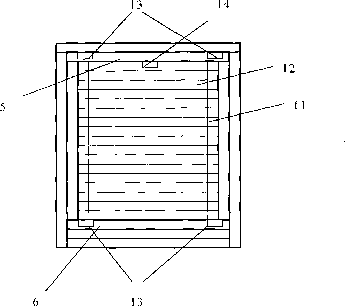
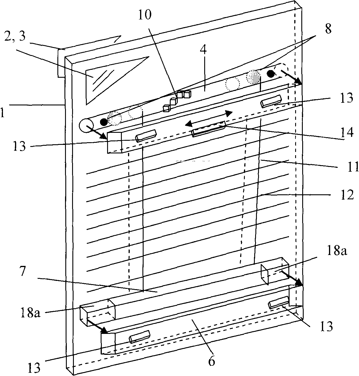
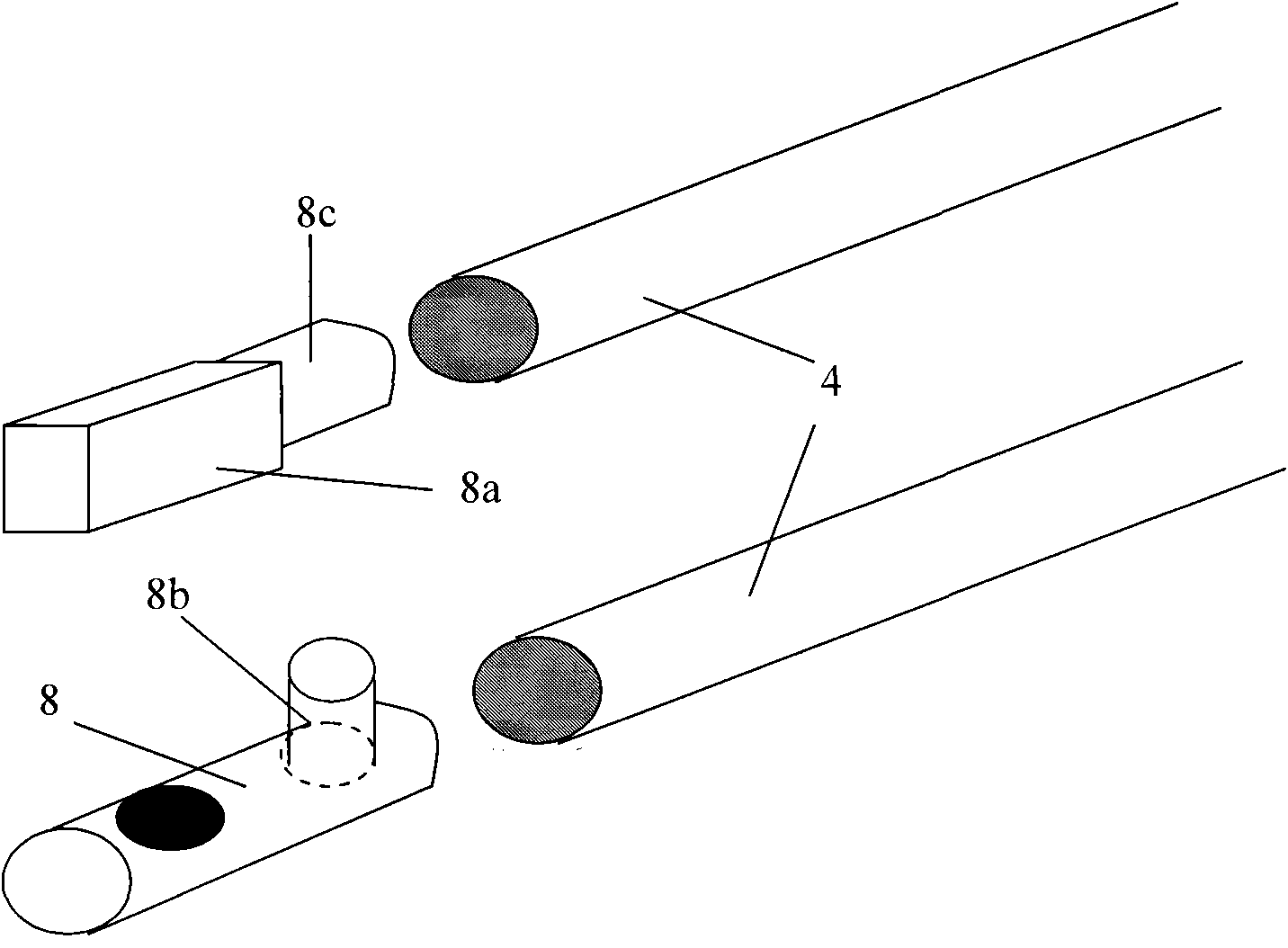
[0023] This invention demonstrates the Figure 1 to Figure 7 Mainly fix the horizontal slats (12) by an appropriate distance by the 11th grid layer mode. This architecture allows the suspension of self-rotating bearing hollow tubes (4), which are connected at the bottom with built-in lower slat sections (7). Each magnet (8b) of the bearing block (8) at both ends of the bearing tube or another kind of two magnets (8a; 18a) built in the upper and lower links, can be mutually positive and negative two-stage suction and external upper and lower hand slats ( 5; 6) inside the magnet (18; 18b) to produce a magnetic fixation effect. The horizontal sliding magnet of the upper adjustment wrench bar (5) can pull the magnet of the bearing hollow tube (4) fixed on the edge of the inner wall. Two types of rotation control devices (23a; 23b) can rotate the slats (12) by 180°. Moving the external upper and lower hand slats (5; 6) can drive the built-in magnet, so that the entire inner louv...


PUM


Abstract

A Venetian blinds with magnetic controller for regulation consists of strings which form ladder (11) which hold the horizontally fitted slats (12) at the appropriate distance. This structure hangs on the freely rotating bearing hollow pipe (4), and at the bottom it is connected to the inner bottom section (7). Each magnet (8b) in the bearings (8) or the inner top / bottom contact magnets (8a; 18 a) are fitted to be in the opposite magnet pole in relation to the poles of the external top / bottom contact magnets (18; 18b) on the external top and bottom regulating batten (5; 6) Magnets which glide horizontally along the external top regulating batten (5) attract magnets fitted at the edges of the freely rotating bearing hollow pipe (4). The rotation controller (23a; 23b) enables rotation of the slats (12) for 180 DEG . By moving the bottom / top external regulating batten (6; 5) together with the related magnets it is possible to move the Venetian blind up or down, including moving of only one side of the top / bottom regulating batten (6;5). Therefore, interaction of the mentioned elements of the invention it is possible to shade any part of the window, including shading diagonally along the window, which will be described in detail later.

Description

technical field [0001] This invention mainly relates to a double-glazed window at a short distance, and a method for adjusting the shutter blades placed in the double-glazed through the external magnetic force. The invention is classified according to International Classification (IPC) number E06B9 / 24. Background technique [0002] The problems that often occur in traditional blinds are: complex adjustment methods on the traditional mechanical structure; short life due to external factors; difficult to disassemble and clean; traditional blinds cannot be moved from the top to the bottom; Noise insulation; and various habitual ways that end customers may need to disassemble and assemble by themselves during installation may lead to a short life span. The above problems that may occur in traditional blinds can be solved by the specially designed magnetic upper and lower hand slats in this patented invention. This makes it possible to rotate the louvers on the inner layer of t...

Claims


Application Information

Patent Timeline
Patent Type & Authority Applications(China)
IPC IPC(8): E06B9/264E06B9/30E06B9/32
CPCE06B2009/2646E06B9/264
Inventor 卓然·马克森
Owner 彭哲彦
Why Eureka
Try Eureka