A device for realizing flow balance control by using a flow balance peristaltic pump

A flow balance, peristaltic pump technology, applied in pump devices, pumps, blood pumps, etc., can solve the problems of harsh use, unable to flow through human blood, unable to achieve flow balance, etc., to achieve flow balance and easy to use.

Active Publication Date: 2020-02-07
GUANGZHOU UNIVERSITY
View PDF3 Cites 0 Cited by
  • Summary
  • Abstract
  • Description
  • Claims
  • Application Information

AI Technical Summary

Problems solved by technology

The invention patent of application number 200610054252.8 records a volume balance and ultrafiltration device for blood purification; the invention patent of application number 201210403479.4 records a balance pump, and the invention patent of application number 201210403480.7 records a continuous flow balance device; The characteristics are: 1. It is installed in the waterway structure inside the complex hemodialysis equipment; 2. It requires huge and complicated mechanical and electrical components; 3. It is only suitable for flowing through the dialysate but not human blood; 4. The pipeline is not Disposable, need to be disinfected and cleaned after each use
[0003] The pump body suitable for flowing through human blood, simple in structure, and disposable, the most common is the roller (or roller) peristaltic pump, which is used in almost all blood purification equipment, but the function of these peristaltic pumps is only to provide Power, but cannot achieve flow balance, all kinds of continuous blood purification equipment (CRRT) only use ordinary peristaltic pumps, and its liquid balance control can only be realized through electronic scales or metering bags, electronic scales take up a lot of space, use demanding

Method used


Image

  • A device for realizing flow balance control by using a flow balance peristaltic pump
  • A device for realizing flow balance control by using a flow balance peristaltic pump
  • A device for realizing flow balance control by using a flow balance peristaltic pump

Examples


Embodiment Construction

[0030] The present invention will be further described in detail in conjunction with the accompanying drawings and specific embodiments.

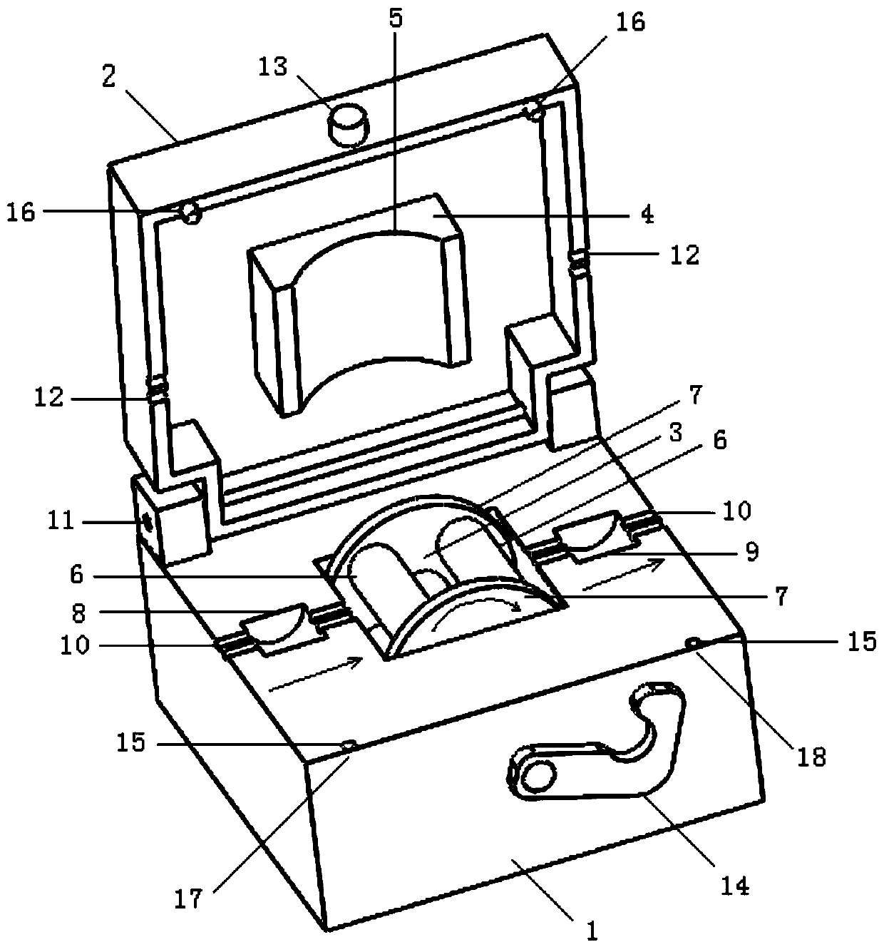
[0031]For the convenience of description, the directions mentioned below are stipulated as follows: the direction of liquid flow is the longitudinal direction, that is, the direction in which the first pump pipe and the second pump pipe are laid, and the longitudinal direction refers to the left and right directions; the direction of the pump head is laid in The lateral direction, the lateral direction refers to the front-rear direction.

[0032] A flow balance peristaltic pump for blood purification, comprising a base, an upper cover, a first pump tube, a second pump tube, a pump head, and two balance cavities. The upper cover covered on the base is rotatably installed on the base, the upper cover is rotatably installed on the base through a rotating shaft, the upper cover and the base are opened in a flipping manner, the structure is simp...


PUM


Abstract

The invention relates to a flow balancing peristaltic pump for blood purification, comprising a base, an upper cover, a first pump pipe, a second pump pipe, a pump head, two balance cavities, and diaphragms; the upper cover covering the base is rotationally fitted to the base, a pump head cavity is arranged in the base, the pump head arranged in the vertical direction is placed in the pump head cavity, the upper cover is provided with a pump head cover used for covering the pump head, the first pump pipe and the second pump pipe are placed transversely in the base, both part of the first pump pipe and part of the second pump pipe compress the peripheral side of the pump head, two sides of the pump head are provided with a limiting plate for limiting the movement of the first and second pump pipes, each balance cavity is internally provided with one diaphragm for diving the balance cavity into a first cavity and a second cavity, the first pump pipe is communicated with the corresponding first cavity, the second pump pipe is communicated with the corresponding second cavity, and the two balance cavities are positioned on two sides of the pump head. The flow balancing peristaltic pump has flow balancing function and belongs to the technical field of blood purification.

Description

technical field [0001] The invention relates to the technical field of blood purification, in particular to a flow balance peristaltic pump for blood purification. Background technique [0002] Blood purification techniques include hemodialysis, filtration, adsorption, and plasma exchange, among which hemodialysis is the most common. An important task of blood purification is the precise removal of excess water from the patient's body, known as ultrafiltration. Technically, the realization of ultrafiltration is accomplished by controlling the flow of two channels of liquid, and the control of the two channels of flow is realized in two parts, that is, the structure of "balance system + ultrafiltration pump". The invention patent of application number 200610054252.8 records a volume balance and ultrafiltration device for blood purification; the invention patent of application number 201210403479.4 records a balance pump, and the invention patent of application number 2012104...

Claims


Application Information

Patent Timeline
Patent Type & Authority Patents(China)
IPC IPC(8): A61M1/10A61M1/16F04B43/12F04B23/04
CPCA61M1/1601A61M1/1621A61M60/113A61M60/268A61M60/279F04B23/04F04B43/12
Inventor 蒋顺忠
Owner GUANGZHOU UNIVERSITY
Why Eureka
Try Eureka