Check patentability & draft patents in minutes with Patsnap Eureka AI!

Signal coder and signal coding method

A signal encoding and signal technology, applied in the field of signal encoder and signal encoding, can solve the problem of large unit circuit and other problems

Inactive Publication Date: 2009-10-07
ACTIONS ZHUHAI TECH CO
View PDF0 Cites 5 Cited by
  • Summary
  • Abstract
  • Description
  • Claims
  • Application Information

AI Technical Summary

Problems solved by technology

[0016] In the existing signal encoder, since the U signal and the V signal are divided into two paths and processed separately, each signal requires a read-only memory and a modulation multiplier, so the number of units in the circuit of the signal encoder and the circuit size Larger

Method used


Image

  • Signal coder and signal coding method
  • Signal coder and signal coding method
  • Signal coder and signal coding method

Examples


Embodiment Construction

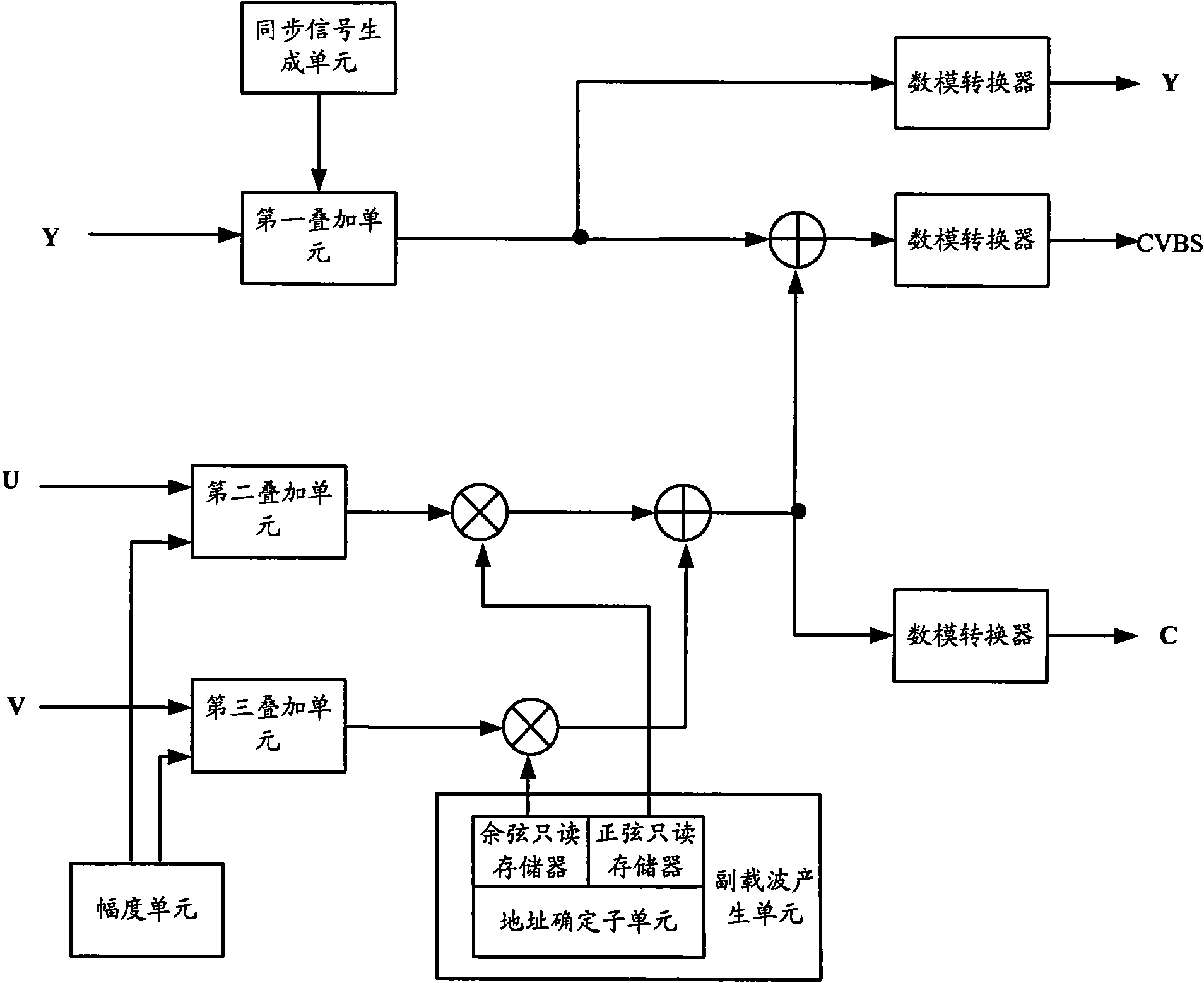
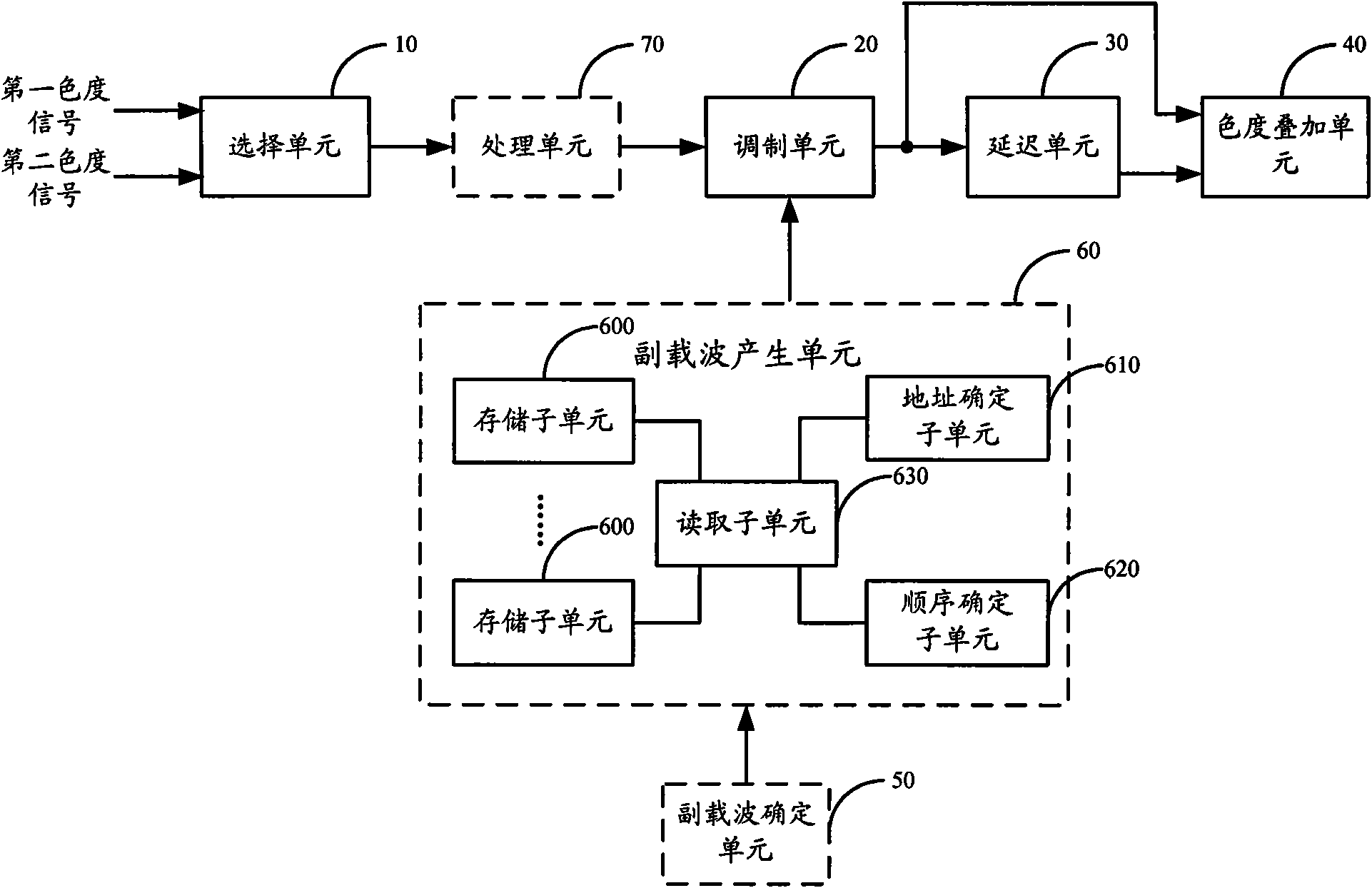
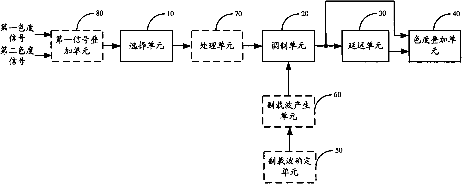
[0037] The signal encoder in an embodiment of the present invention includes: a selection unit, configured to alternately output the first chrominance signal and the second chrominance signal according to a predetermined period; a modulation unit, configured to alternately output the first chrominance signal according to the predetermined period The first subcarrier corresponding to the first chrominance signal modulates the first chrominance signal, and the second subcarrier corresponding to the second chrominance signal modulates the second chrominance signal; The delay unit is used to delay the modulated first chrominance signal to output by the predetermined period; the chrominance superposition unit is used to perform the delayed first chrominance signal and the modulated second chrominance signal overlay. Since the first chrominance signal and the second chrominance signal are multiplexed, only one modulation unit is needed, thereby reducing the number of units in the ci...


PUM


Abstract

The invention belongs to the signal treatment field, especially relates to a signal coder and signal coding method capable of reducing the circuit cost and circuit scale. The signal coder of the embodiment comprises: a selection unit for alternatively outputting a first chrominance signal and a second chrominance signal according to preset cycle; a modulation unit for alternatively modulating the first chrominance signal by the first subcarrier corresponding with the first chrominance signal according to the preset cycle and modulating the second chrominance signal by the second subcarrier corresponding with the second chrominance signal; a delay unit for delaying the output of the modulated first chrominance signal; a chrominance superposition unit for superposing the delayed first chrominance signal and modulated second chrominance. The signal coder of the embodiment can reduce the number of the unit in the circuit and the volume of the circuit.

Description

technical field [0001] The invention relates to the field of signal processing, in particular to a signal encoder and a signal encoding method. Background technique [0002] The full TV signal consists of image brightness information, chrominance information, horizontal synchronous signal, vertical synchronous signal and color burst signal. In order to be compatible with black-and-white TV signals that only contain luminance information, the bandwidth of chrominance signals is compressed by using the insensitivity of human eyes to color changes. The chrominance signal is then modulated into the high frequency part of the frequency band using a subcarrier. By reasonably selecting the frequency of the subcarrier, the luminance information and chrominance information can be placed at intervals on the frequency band, so as to achieve the purpose of multiplexing the frequency band without interfering with each other. [0003] YUV (that is, YCrCb) is a color coding method (belon...

Claims


Application Information

Patent Timeline
IPC IPC(8): H04N11/04H04N9/45
Inventor 王灿王茜
Owner ACTIONS ZHUHAI TECH CO
Features
  • R&D
  • Intellectual Property
  • Life Sciences
  • Materials
  • Tech Scout
  • Unparalleled Data Quality
  • Higher Quality Content
  • 60% Fewer Hallucinations
Learn More