Light

A lighting equipment, edge technology, applied in the direction of lighting and heating equipment, lighting devices, components of lighting devices, etc., can solve problems such as difficulties

Inactive Publication Date: 2009-10-07
IBV HLDG
View PDF1 Cites 8 Cited by
  • Summary
  • Abstract
  • Description
  • Claims
  • Application Information

AI Technical Summary

Problems solved by technology

Transparent or at least light-transmitting plastics, such as they are intended for the light output of gas discharge tubes or similar elongated luminaires, however present considerable difficulties due to the consequent high thermal expansion, which imposes on the housings Problematic fit and bonding between body parts and especially a sealed connection between two housing parts

Method used


Image

  • Light
  • Light
  • Light

Examples


Embodiment Construction

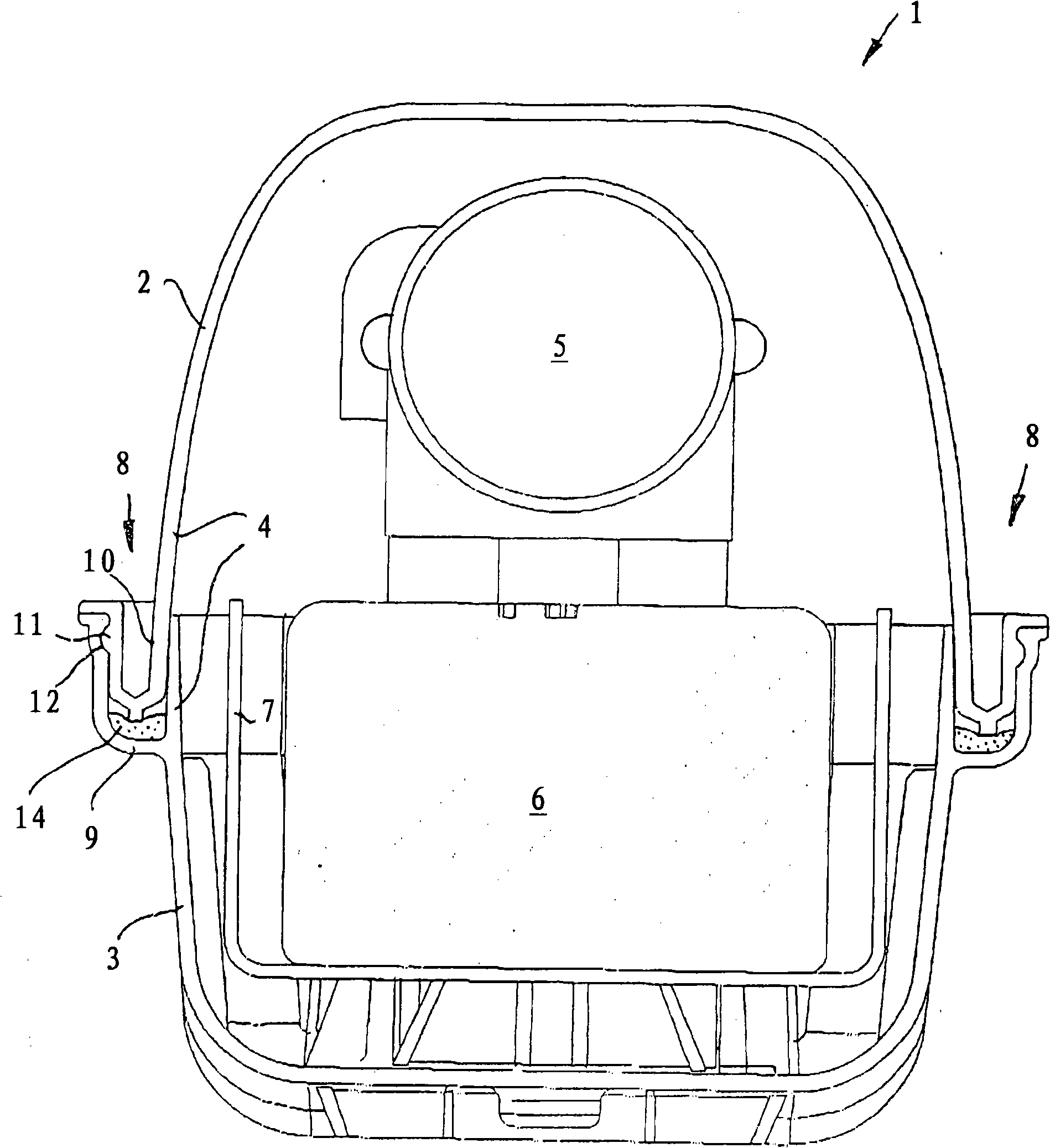
[0012] have basis figure 1 The lighting device 1 in cross-section has an elongated housing, indicated generally with 4, composed of a connecting part 2 and a base part 3, for accommodating a gas discharge lamp 5 located inside, wherein the housing The body 4 extends prismatically over almost its entire length and is closed cap-shaped at each end. In addition to housing the gas discharge lamp 5, the base part 3 also accommodates further (electrical) devices, including the ballast 6 and the associated shielding plate 7, which serves to reduce the risk of damage in the area of ​​the ballast. Heat radiation from the ballast to the base 3 . The base part 3 can be used for fixed mounting of the lighting device on a wall or ceiling, while the connecting parts 2 of the individual fitting parts which are not usually provided with the lighting device are designed to be freely removable.

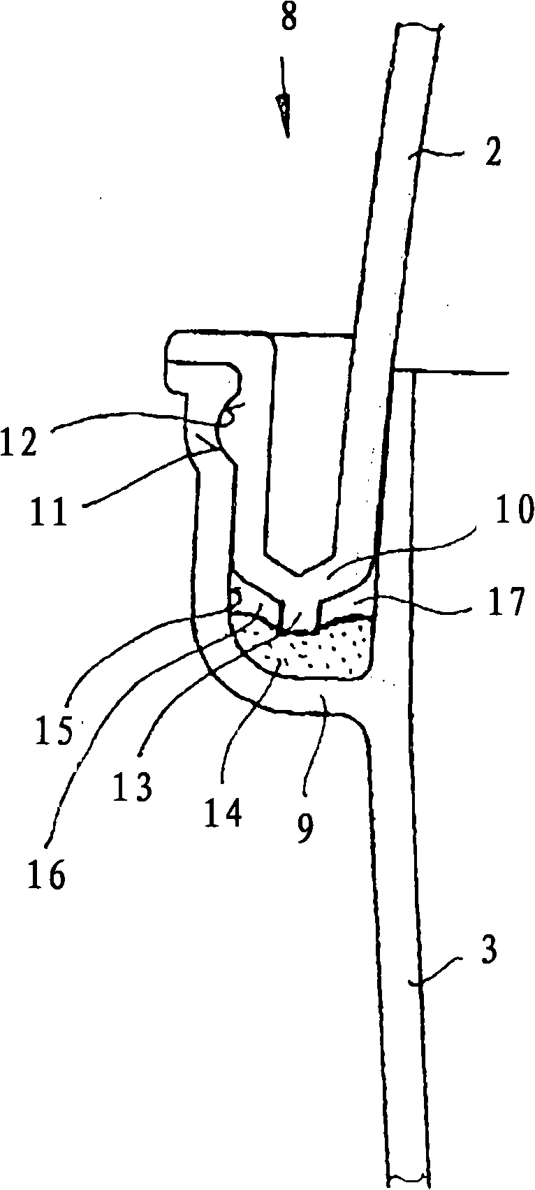
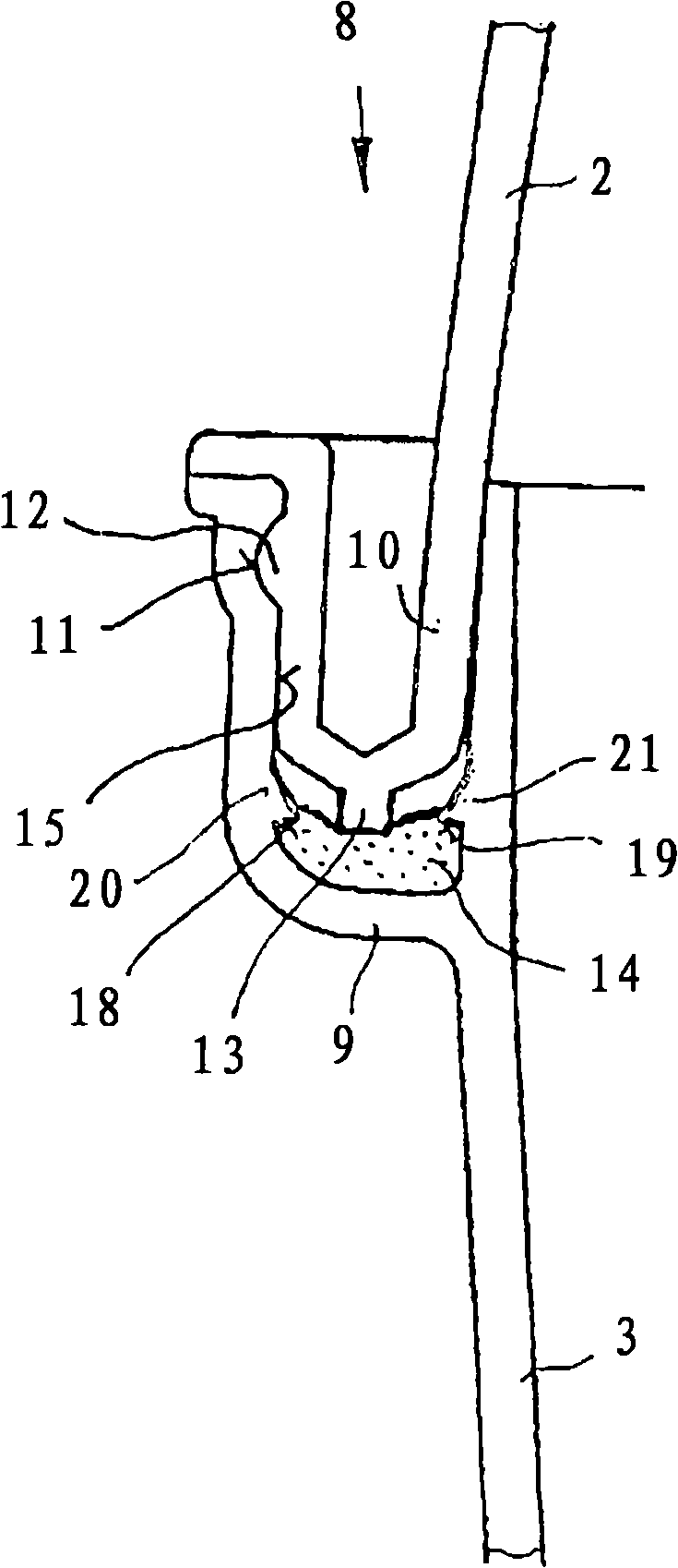
[0013] The connecting part 2 and the base part 3 are detachably connected to one another via a ci...


PUM


Abstract

The invention relates to a light (1) especially a wall or ceiling light protected from spray water and used to receive at least one long gas discharge lamp (5), said light comprising a closed housing formed by an at least transparent base part (3) which can be mounted in a fixed location and holds electrical devices, and an at least transparent coupling part (2). The base part (3) and the coupling part (2) are injection-moulded from the same charges of thermoplastic material in a common mould which is essentially symmetrical in terms of the injection process, and overlap along peripheral edges on both sides, one edge being an insertion edge (10) and the other edge being embodied as a U-shaped receiving element (9) for receiving the insertion edge (10). According to the invention, taking into consideration the characteristic features of the transparent or translucent plastic material and the requirements of large-scale production, the light is designed in such a way that the U-shaped receiving element (9) comprises a seal (14) consisting of an elastomer foam forming a smooth outer skin, and the inner wall (15) of the light is provided with a surface structure improving the adhesion, for receiving the seal (14).

Description

technical field [0001] The invention relates to a lighting device according to the preamble of claim 1 and a method according to the preamble of claim 8 as known from German patent application DE 103 33 980 A1. Background technique [0002] Lighting devices of this type, which can in principle be produced in an injection molding process from thermoplastics, in particular polypropylene, are mainly produced as series products in mass production and have corresponding advantages in terms of manufacture and materials High cost pressure. Transparent or at least light-transmitting plastics, such as they are intended for the light output of gas discharge tubes or similar elongated luminaires, however present considerable difficulties due to the consequent high thermal expansion which imposes on the housings Fitting and bonding between the body parts and especially the sealing connection between two housing parts pose problems. [0003] In order to match the materials of the upper...

Claims


Application Information

Patent Timeline
Patent Type & Authority Applications(China)
IPC IPC(8): F21V31/00F21Y103/00
CPCF21V17/164F21V31/00B29C45/26B29C45/0053B29C59/142F21V3/04F21Y2103/00B29C2045/2683B29L2031/747F21V15/01F21V31/005
Inventor J·冯霍夫
Owner IBV HLDG
Why Eureka
Try Eureka