
Automatic grouting control device of push bench and method

An automatic control device and pipe jacking machine technology, which is applied in the installation of bolts, shaft equipment, earthwork drilling and mining, etc., can solve the problems of inability to control land subsidence, grout overflow and grouting amount, and long construction period, etc., to achieve Reduce the effect of poor control of grouting volume, reduce working pressure, and avoid ground subsidence

Inactive Publication Date: 2009-10-14
SHANGHAI TUNNEL ENGINEERING CO. LTD.
View PDF0 Cites 17 Cited by
  • Summary
  • Abstract
  • Description
  • Claims
  • Application Information

AI Technical Summary

Problems solved by technology

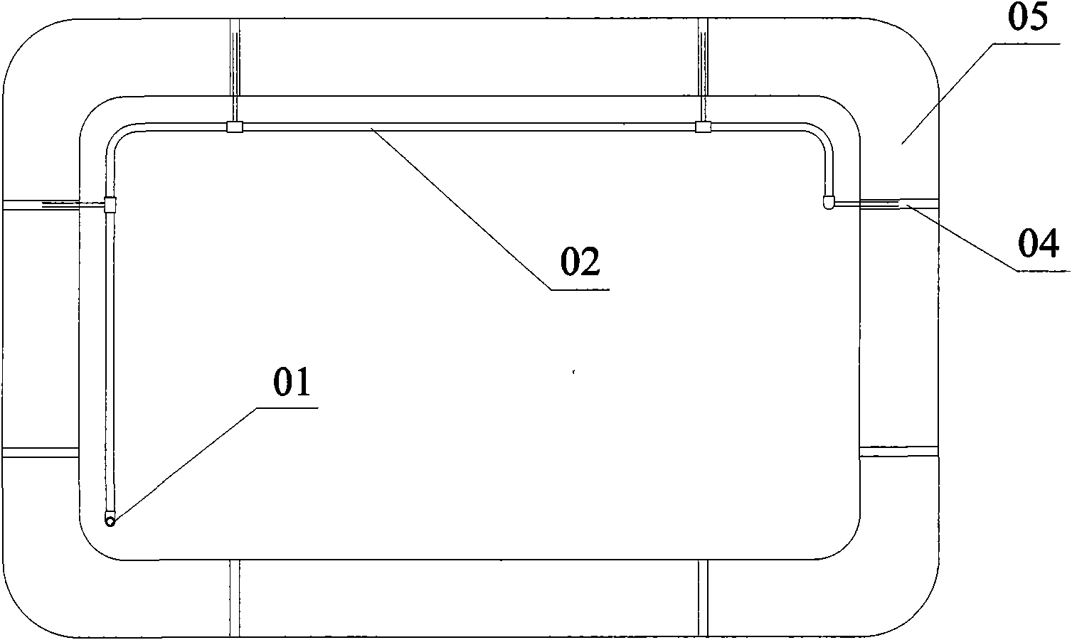
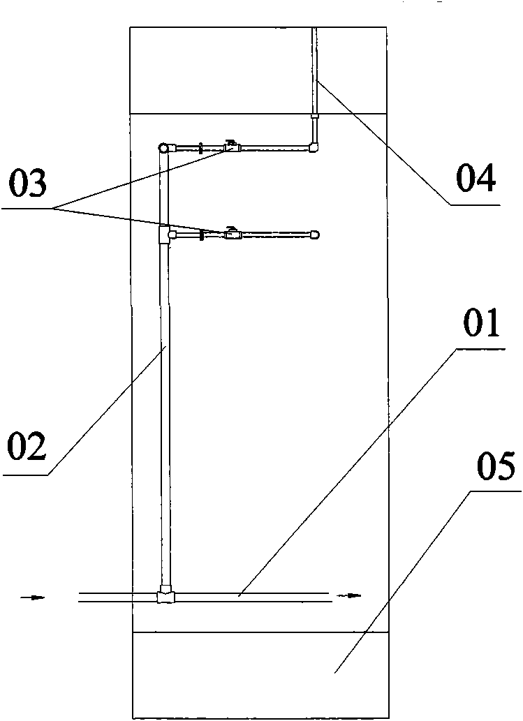
[0005] The existing grouting system of the pipe jacking machine is completely determined by manual judgment when and where to start the grouting, the duration of the grouting, etc. At the same time, the manual operation of the grouting pump and the opening and closing of the manual valve 03 of each grouting port 04 is adopted, so it not only There is a shortcoming of relying too much on the subjective judgment of the operator, resulting in the overflow of grout or insufficient grouting due to the negligence of on-site personnel, so that the ground settlement cannot be well controlled, and the operator of the grouting pump on the ground has the same relationship with the underground manual valve 03 Difficulty and untimely communication between operators, manual operation of multiple grouting manual valves 03, etc. have brought slow response speed, low operation efficiency, long construction period and coordination to the existing pipe jacking machine grouting system. Flaws of difficult command

Method used


Image

  • Automatic grouting control device of push bench and method
  • Automatic grouting control device of push bench and method
  • Automatic grouting control device of push bench and method

Examples


Embodiment Construction

[0031] The present invention will be described in further detail below in conjunction with the accompanying drawings and specific embodiments.

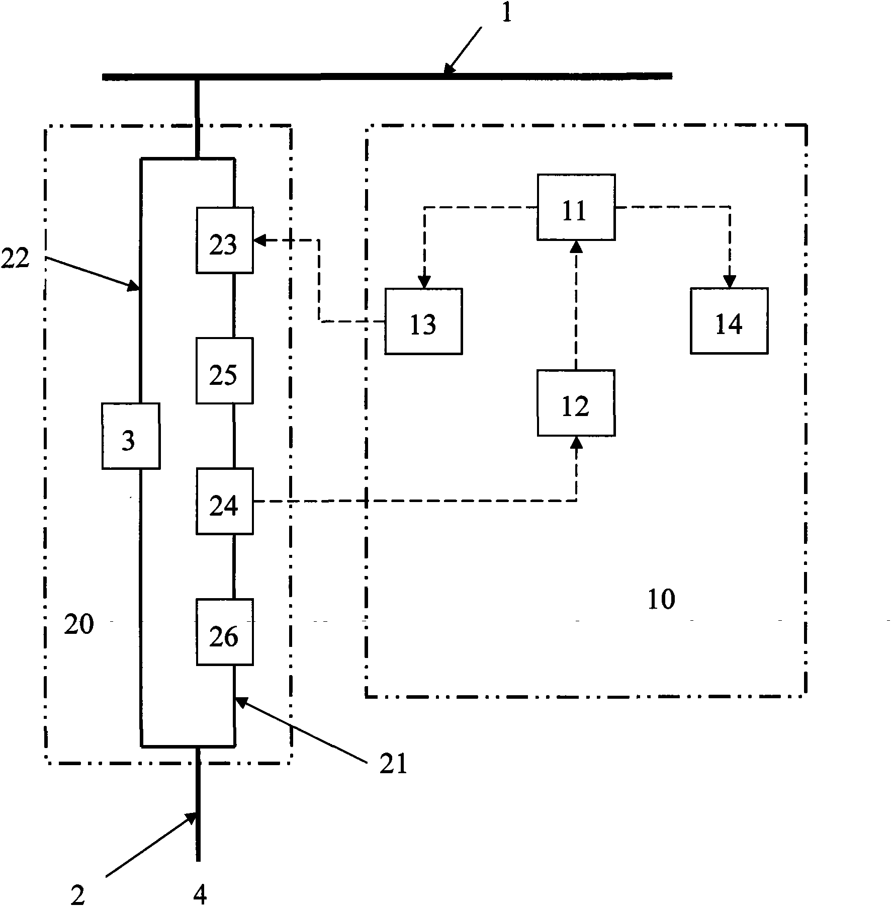
[0032] See first image 3 The structure schematic diagram of the present invention shows that the automatic grouting control device of the pipe jacking machine includes a grouting main pipe 1 connected to the grout storage tank and a grouting pump, a grouting sub-pipe 2 connected to the grouting main pipe, several grouting components 20 and a control Component 10. The grout storage tank and the grouting pump are arranged on the ground (not shown in the figure), and the grouting main pipe 1 leads from the ground to the pipe joints ( image 3 not shown in the figure 1), the grout storage tank is used to store the prepared grouting materials, the grouting pump provides the grouting power of the pipe jacking machine, and the grouting main pipe 1 is the main pipeline for transmitting the grouting materials; at each pipe joint, the grouti...


PUM


Abstract

The invention relates to an automatic grouting control device of a push bench, comprising a grouting master pipe, a grouting dividing pipe, a plurality of grouting components and a control component; the grouting component is arranged at the tail end of the grouting dividing pipe and comprises two grouting branch pipes which are parallelly connected; one grouting branch pipe is sequentially provided with a pneumatic valve used for on and off of the grouting branch pipe and a pressure sensor used for detecting grouting pressure; the other grouting branch pipe is provided with a manual valve; the control component comprises an industrial computer, an input module and an output module; the industrial computer can preset the pressure values of all the grouting ports and deviation range and carry out operation and storage of values; the input module converts pressure signals input by the pressure sensor into digital signals and transmits the digital signals to the industrial computer; and the output module digital signals transmitted by the industrial computer into trigger signals so as to control the opening and closing of the pneumatic valve. The automatic control device realizes automatic grouting process by adopting grouting pressure as control parameters, has the advantages of fast response, stable grouting pressure and high construction efficiency and is applicable to grouting construction of the push bench.

Description

Technical field: [0001] The invention relates to a grouting system of a pipe jacking machine for tunnel construction, in particular to an automatic grouting control device and method for a pipe jacking machine. Background technique: [0002] In the construction of underground tunnel engineering, grouting is required between the pipe joints and the soil that are jacked in by the pipe jacking machine and connected front and back to form a mud sleeve to reduce the resistance between the pipe joints and the soil, and at the same time fill the jacking construction The gap formed between the pipe joint and the soil can control the ground subsidence and ensure the smooth advancement of the pipe jacking machine. This work is done by the grouting system of the pipe jacking machine. [0003] The grouting system of the existing pipe jacking machine consists of a grout storage tank, a grouting pump, a grouting main pipe, a grouting branch pipe, and a manual valve. Please refer to figu...

Claims


Application Information

Patent Timeline
IPC IPC(8): E21D11/00E21D20/02
Inventor 温锁林徐连刚黎燕舒刚强田军
Owner SHANGHAI TUNNEL ENGINEERING CO. LTD.
Learn More