Rotary-type self-latching safety braking device and working method thereof

A safety braking and wheel-type technology, applied in the direction of brake type, building structure support, building structure support, etc., can solve the problems of hidden safety hazards, many fault points, slow lifting or lowering process, etc., and achieve good sealing performance and control The effect of short moving distance and compact structure

Inactive Publication Date: 2009-10-14
SHENZHEN TECHEN SCI & TECH CO LTD
View PDF0 Cites 8 Cited by
  • Summary
  • Abstract
  • Description
  • Claims
  • Application Information

AI Technical Summary

Problems solved by technology

[0002] The building-attached lifting scaffold is the equipment used in the construction of high-rise and super high-rise buildings. During use or operation, its lifting or lowering process is carried out slowly. If it falls quickly, it is an abnormal situation, which will cause high-altitude falling or equipment damage. Accidents, so the equipment must be equipped with a self-locking safety brake device to ensure safe use
[0003] Building construction elevators are also equipment used in high-rise and super high-rise building construction. During use or operation, their rise and fall are also slow. If they fall quickly, it will cause high-altitude fall or equipment damage accidents. Therefore, equipment must also be installed Self-locking safety brake device
[0004] Many of the material conveying equipment or conveyor belts used in the machinery industry and metallurgical industry, and the vehicles in mine tunnels, ships and oceans, etc., require slow uniform speed or slow intermittent operation. Casualties or equipment damage accidents, so equipment self-locking safety braking devices must be installed
[0005] The seat belt used on the vehicle can be pulled slowly during the normal movement of the occupant, but when the vehicle brakes suddenly, the upper body of the occupant leans forward sharply, and the seat belt is pulled out quickly, which will cause personal injury, so a self-locking safety brake must be installed The device clips the seat belt to ensure the safety of the occupants
[0006] At present, many engineering fields such as construction, machinery, metallurgy, mines, vehicles, ships, etc. operate at a slow uniform speed or in slow intervals. Fast operation is an abnormal condition, and most of the equipment that will cause casualties or equipment damage accidents are equipped with self-locking safety systems. However, some of these self-locking safety brake devices have complex structures and high failure rates, which affect the normal working process. Needle and follow-up device, at the same time, it is easy to cause jamming during the lowering process of the frame. Some operators artificially invalidate the swing needle, which brings major safety hazards; some self-locking safety brake devices are large in size and use for a period of time Afterwards, it is easy to fail. Once an accident occurs, it is easy to cause a high-altitude fall or equipment damage accident, which will bring safety hazards. For example, the self-locking safety brake device of a construction elevator is equipped with a hammer device that uses the centrifugal force generated by rapid rotation to brake. , which are bulky and require regular maintenance; some self-locking safety brake devices have complex structures and require high manufacturing precision, such as the automatic trigger brake devices on seat belts used in many cars; some self-locking safety brake devices The device is controlled by electromechanical integration, which is not only complicated, but also high in cost and has many failure points, such as many conveyor belts and material carriers in the machinery industry and metallurgical industry.

Method used


Image

  • Rotary-type self-latching safety braking device and working method thereof
  • Rotary-type self-latching safety braking device and working method thereof
  • Rotary-type self-latching safety braking device and working method thereof

Examples


Embodiment 1

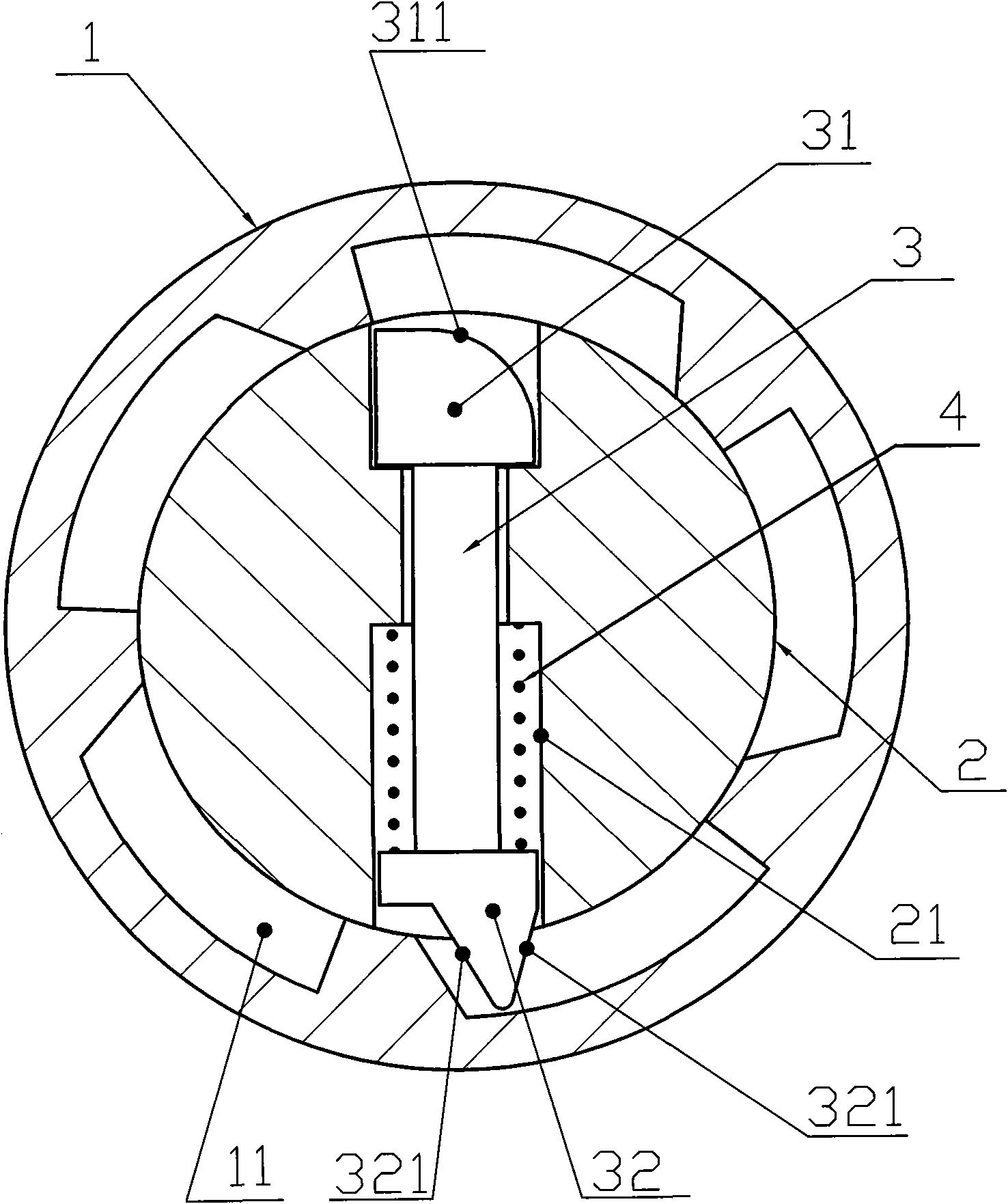
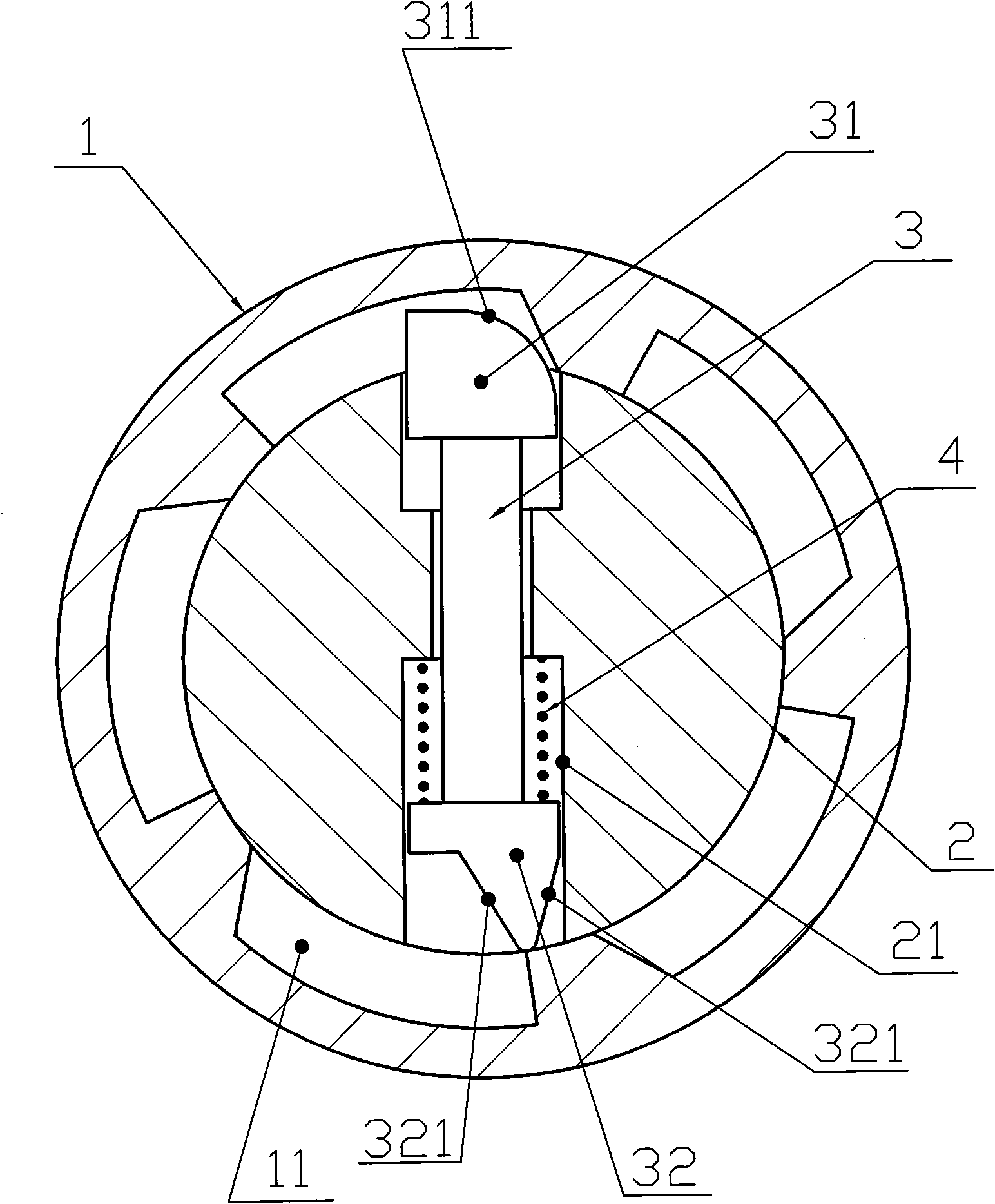
[0030] Such as figure 1 and figure 2 As shown, a wheel-type self-locking safety braking device provided in this example includes a wheel 1, a wheel shaft 2 that is arranged in the wheel 1 and rotates with the inner cylindrical surface of the wheel 1. The inner cylindrical surface of the wheel 1 is provided with a number of key grooves 11, and the wheel shaft 2 is provided with a chute 21 corresponding to the key groove 11 and radially penetrating, and the chute 21 is provided with a The movable pin key 3 of two-way sliding, described movable pin key 3 is provided with the pin key reset device 4 that can make this movable pin key 3 reset, and this reset device 4 can specifically be a compression spring, and the movable pin key 3 The length is equal to or slightly less than the sum of the diameter of the rotating shaft 2 and the depth of the key groove 11 . When the top 31 of the movable pin key 3 is pushed into the runner keyway 11, the tail end 32 will escape from the runne...

Embodiment 2

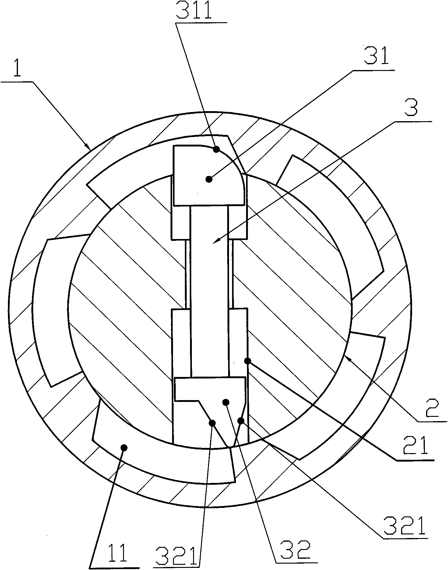
[0035] Such as image 3 As shown, this example is roughly the same as Embodiment 1, except that the pin key reset device 4 is omitted, the working position of the radial chute 21 of the wheel shaft 2 is set at a vertical position, and the top end of the movable pin key 3 31 is arranged on the top of described chute 21, and the tail end 32 of described movable pin key 3 is arranged on the bottom of described chute 21, utilizes the action field that the gravity of movable pin key 3 produces to promote its self reset.

[0036] Such as Figure 1 ~ Figure 3 As shown, the present invention also provides a working method of a wheel-type self-locking safety brake device involved in Embodiment 1 and Embodiment 2: when the wheel 1 rotates forward slowly, the side of the keyway 11 on the inner cylindrical surface of the wheel 1 Rib presses the slope 311 of the top 31 of the movable pin key 3, and the movable pin key 3 slides along the radial chute 21 of the wheel shaft 2 toward its tail...

Embodiment 3

[0039] refer to Figure 1 to Figure 5 , the present invention also provides an example of a wheel-type self-locking safety brake device applied in the field of attached lifting scaffolding, that is, a wheel anti-falling device of an attached lifting scaffold, which includes a guide rail 5 and a guide seat 6, The guide rail 5 is connected with the guide seat 6 by a sliding sleeve, the guide rail 5 is provided with cross bars 51 at intervals, and the guide seat 5 is provided with a runner 1 that can rotate and engage with the cross bar 51; A kind of rotating wheel type self-locking safety braking device as mentioned above is set on the hub 12.

[0040] The working method of the runner anti-falling device of an attached lifting scaffold provided by the present invention is as follows: when the scaffold is slowly lifted, the runner 1 engages with the spaced cross bar 51 set on the guide rail 5 and rotates forward slowly; the scaffold slowly descends At the same time, the running ...


PUM


Abstract

The invention relates to a rotary-type self-latching safety braking device and a working method thereof. The rotary-type self-latching safety braking device comprises a rotating wheel, an axle, an axle base, a movable pin key and a pin key resetting device. An inner cylindrical surface of the rotating wheel, which is matched with the axle, is provided with a plurality of key slots. The axle is provided with a radial sliding chute which is internally provided with the movable pin key and the pin key resetting device. During the slow rotating process of the rotating wheel, the movable pin key makes slow radial reciprocating motion in the radial sliding chute of the axle correspondingly, and the axle can normally rotate; and when the rotation speed of the rotating wheel suddenly increases, the reciprocating motion of the movable pin key is damaged, one end of the movable pin key is propped into the key slot of the rotating wheel, and the rotating wheel is self-latching braked immediately. The invention has compact structure, simple construction, small volume, good sealing property, sensitive action, high reliability, short braking distance and safe use, and is applicable to the engineering fields such as building, machinery, metallurgy, mining, vehicles, vessels and the like. When in normal work, the rotary-type self-latching safety braking device slowly runs; and when in dangerous situations, the device fast runs, and the self-latching safety braking device in running is stopped immediately.

Description

technical field [0001] The invention relates to a wheel-type self-locking safety braking device and its working method, which is suitable for engineering fields such as construction, machinery, metallurgy, mines, vehicles, ships, etc., which operate at a slow speed during normal operation and dangerous conditions during fast operation. Self-locking safety braking device that must stop running immediately. Background technique [0002] The building-attached lifting scaffold is the equipment used in the construction of high-rise and super high-rise buildings. During use or operation, its lifting or lowering process is carried out slowly. If it falls quickly, it is an abnormal situation, which will cause high-altitude falling or equipment damage. Accidents, so the equipment must be equipped with a self-locking safety brake device to ensure safe use. [0003] Building construction elevators are also equipment used in high-rise and super high-rise building construction. During u...

Claims


Application Information

Patent Timeline
IPC IPC(8): F16D63/00E04G3/32
Inventor 沈海晏张爱武余志钢杨铁柱
Owner SHENZHEN TECHEN SCI & TECH CO LTD
Why Eureka
Try Eureka