Reflective cup for LED lamp

A technology of LED lamps and reflector cups, applied in the field of reflector cups, can solve the problems of not being able to fully utilize light energy, unsuitable, unsuitable for lighting systems, etc.

Inactive Publication Date: 2009-10-14
SOUTH CHINA UNIV OF TECH
View PDF0 Cites 23 Cited by
  • Summary
  • Abstract
  • Description
  • Claims
  • Application Information

AI Technical Summary

Problems solved by technology

However, there are still many shortcomings in the current LEDs: the total light energy of a single LED is low, and most LED products have a Lambertian distribution luminous curve with a large divergence angle (180°), so they are not suitable for lighting systems alone
Although these methods based on the principle of traditional imaging optics solve the problem of achieving uniform illumination in a specific illumination area, due to their own nature limitations, there is a specific collection angle, so they cannot fully utilize the light energy emitted by LEDs.
At the same time, various solutions require a large number of optical components to cooperate with each other to form an optical system to realize their functions, so they are relatively complicated and not suitable for miniaturized systems. However, miniaturization is increasi

Method used


Image

  • Reflective cup for LED lamp
  • Reflective cup for LED lamp
  • Reflective cup for LED lamp

Examples


Embodiment Construction

[0052] The implementation of the present invention will be further described in detail below in conjunction with the accompanying drawings.

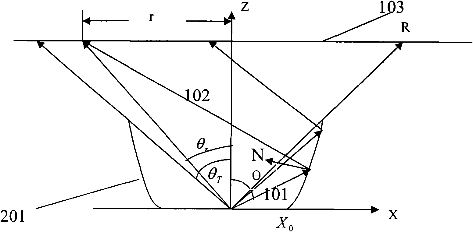
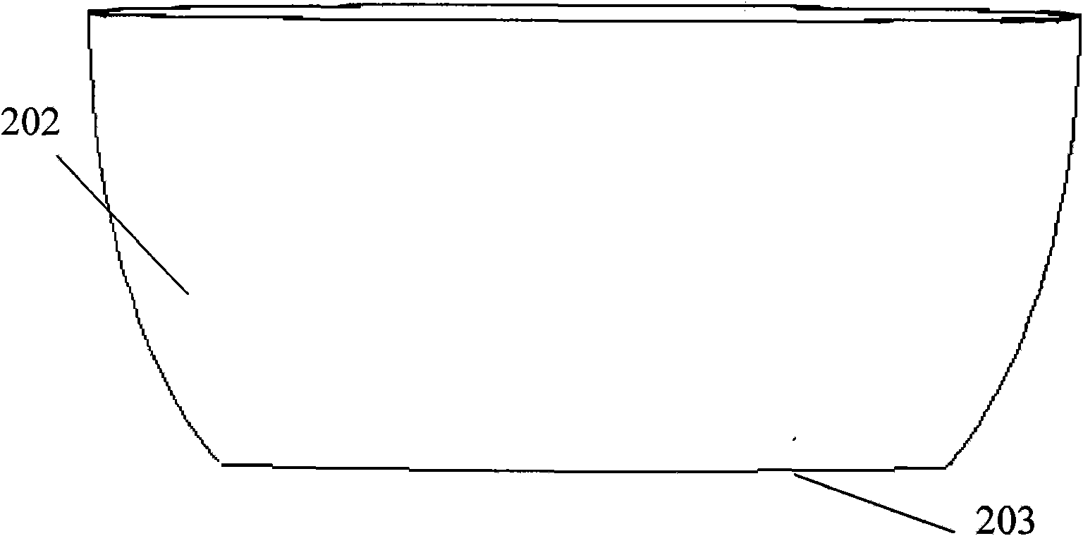
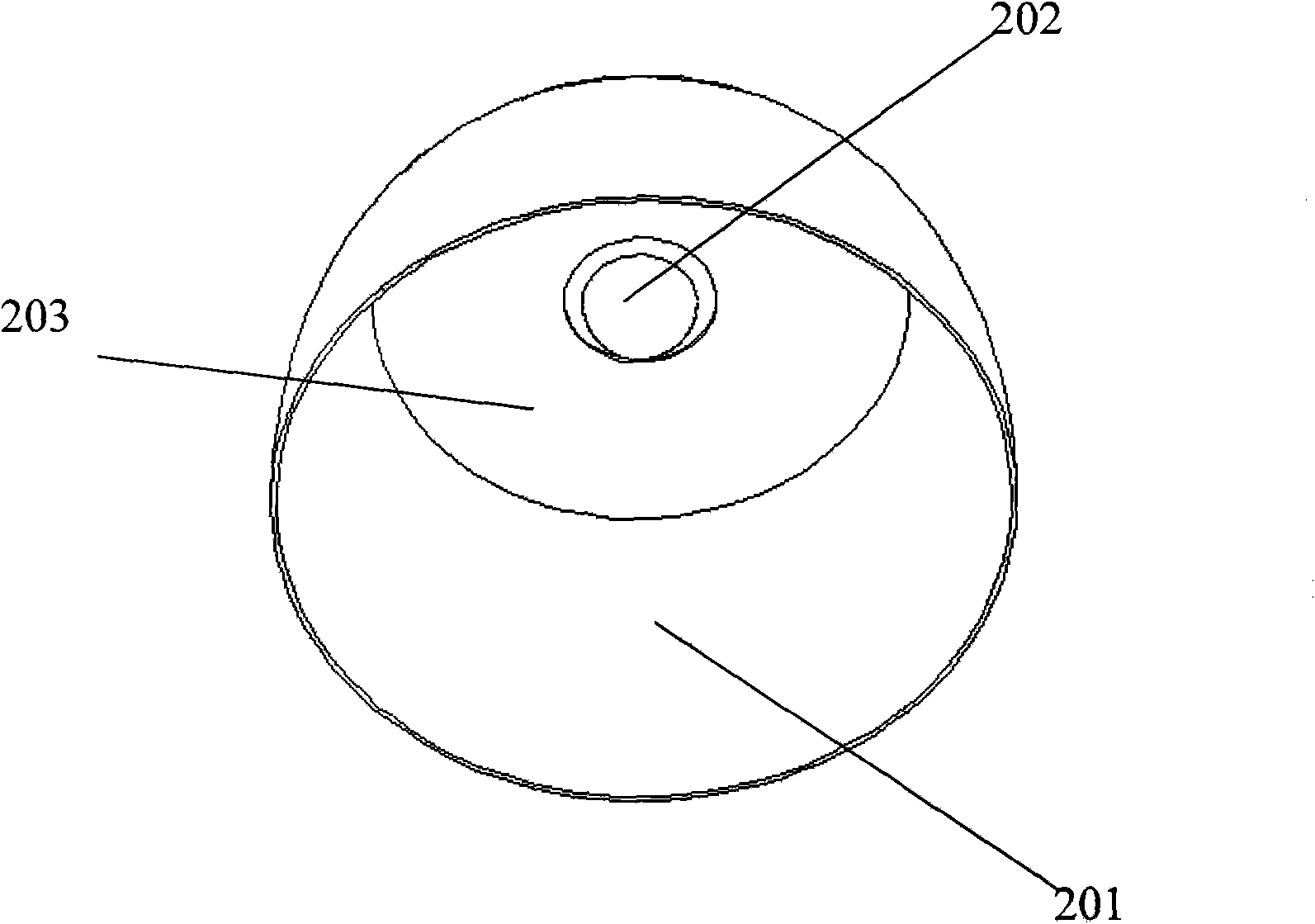
[0053] The reflective cup used for LED lamps includes a reflective surface 201 and an annular bottom surface 203. The LED 202 is placed in the center of the bottom surface. Part of the light from the LED is directly emitted from the opening of the reflective cup. This part of the light reaches the target plane to form an initial lighting surface. The reflective surface of the cup reflects the rest of the light to the initial lighting surface, so that the energy of the two parts of light is superimposed to form a uniform lighting surface. The reflective surface of the reflective cup is a free-form surface, and the shape of the free-form surface is determined by the following method.

[0054] In this embodiment, the curve is determined through the following steps:

[0055] The light source adopts Lambertian LED, that is, the light intensit...


PUM


Abstract

The invention provides a reflective cup for a LED lamp, comprising a reflection surface and a bottom surface; the LED is positioned in the center of the bottom surface, a part of light of the LED is emitted from an opening of the reflective cup directly, the part of light reaches an objective plane to form an initial illumination plane, the other part of light is reflected by the reflective surface of the reflective cup to the initial illumination plane, a uniform lighting plane is formed by the energy overlay of the two parts of light, the reflective surface of the reflective cup is a free surface, the shape of the free surface is determined by the following method: the reflective cup is in central axial symmetric shape, the section crossing the central axis of the reflective cup is taken as a datum plane, coordinates is established, the central axis is Z axis, the original point is on the central axis, the LED light source is positioned at the original point, the direction passing through the original point and is vertical to the central axis is X axis, a curved line on the XZ plane corresponding to the free surface is rotated for 360 degrees around the Z axis, then the shape of the free surface is obtained. The reflective cup of the invention is simple and compact in structure and the LED optical uniformity is good.

Description

technical field [0001] The invention belongs to the field of optical technology and lighting technology, and in particular relates to a reflective cup used for LED lamps. Background technique [0002] As one of the greatest inventions in human history, artificial light source has had a profound impact on the evolution of human civilization, and it has also continued to improve with the development of science and technology. As a new artificial light source, LED has shown a very broad application prospect due to its small size, low energy consumption, good monochromaticity and other advantages. However, there are still many shortcomings in the current LEDs: the total light energy of a single LED is low, and most LED products have a Lambertian distribution luminous curve with a large divergence angle (180°), so they are not suitable for lighting systems alone . In most applications, people need additional optics to cooperate with LEDs to achieve uniform illumination in the i...

Claims


Application Information

Patent Timeline
IPC IPC(8): F21V7/04F21V7/10F21V19/00H01L33/00F21Y101/02F21Y115/10
Inventor 王洪张奇辉王海宏张小凡纪玲玲
Owner SOUTH CHINA UNIV OF TECH
Why Eureka
Try Eureka