Breathing-type shoe pads
An insole and end face technology, applied in insoles, footwear, clothing, etc., can solve the problems of poor ventilation efficiency, high production cost, and inability to conduct large-scale ventilation, so as to improve the speed and volume of breathing air and reduce production costs. , the effect of simple structure
- Summary
- Abstract
- Description
- Claims
- Application Information
AI Technical Summary
Problems solved by technology
Method used
Image
Examples
no. 1 example
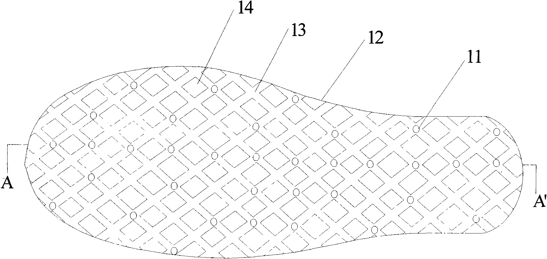
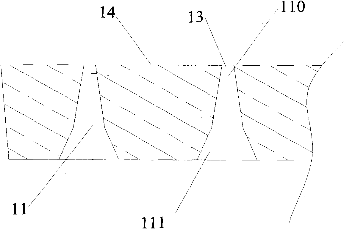
[0024] Such as figure 1 , figure 2 and image 3 As shown, the breathing insole has elasticity, and several through-holes 11 are arranged on the upper and lower sides of the breathing insole, and a first air guide groove 13 is arranged on the upper end surface 12 of the breathing insole. The first air guide groove 13 communicates with each of the through holes 11 , and the first air guide groove 13 forms several bosses 14 on the upper end surface 12 of the breathing insole 1 . The through hole 11 is trumpet-shaped, and the diameter of the through hole 11 gradually increases along the direction of the upper hole 110 to the lower hole 111, that is, from the direction of the upper end surface 12 to the lower end surface 15, the diameter of the through hole 11 The hole diameter gradually increases, the through holes 11 communicate through the first air guide groove 13, and form a mesh on the upper end surface 12 of the breathing insole.
[0025] When the breathing insole 1 is m...
no. 2 example
[0031] Such as Figure 4 and Figure 5 As shown, the breathing insole has elasticity, and the breathing insole is provided with a plurality of through holes 11 passing through the breathing insole, and the upper end surface 12 of the breathing insole is provided with a first air guide groove 13, The first air guide groove 13 communicates with each of the through holes 11 , and the first air guide groove 13 forms several bosses 14 on the upper end surface 12 of the breathing insole. The through hole 11 is trumpet-shaped, and the diameter of the through hole 11 gradually increases along the direction of the upper hole 110 to the lower hole 111, that is, from the direction of the upper end surface 12 to the lower end surface 15, the diameter of the through hole 11 The pore size gradually increases. A second air guide groove 16 is provided on the lower end surface 15 of the breathing insole, and the second air guide groove 16 communicates with each of the through holes 11 . Whe...
no. 3 example
[0038] Such as Figure 6 As shown, the present invention also proposes an embodiment on the basis of the above-mentioned embodiments, the lower end surface 15 of the breathing insole is provided with a cavity 17 at the heel position, and the cavity wall of the cavity 17 is provided with the through hole 11 , the cavity 17 communicates with the through hole 11 through the second air guiding groove 16 . Other structures and configuration relationships are the same as those in the above-mentioned embodiments, and will not be repeated here.
[0039] In the present embodiment, since the cavity 17 is relatively large, it can accommodate more air, thereby generating a larger airflow volume during exhalation and inhalation, so that the breathing insole can expel sweat more quickly.
[0040] In the above embodiments, the number, shape and distribution of the through holes 13 can be set as required. Such as Figure 6 As shown, the density of the through holes 13 arranged at the conta...
PUM
 Abstract
Description
Claims
Application Information
 - R&D
- Intellectual Property
- Life Sciences
- Materials
- Tech Scout
- Unparalleled Data Quality
- Higher Quality Content
- 60% Fewer Hallucinations
Browse by: Latest US Patents, China's latest patents, Technical Efficacy Thesaurus, Application Domain, Technology Topic, Popular Technical Reports.
© 2025 PatSnap. All rights reserved.Legal|Privacy policy|Modern Slavery Act Transparency Statement|Sitemap|About US| Contact US: help@patsnap.com


