Self assembled ultramicro fan

An assembled, ultra-micro technology, applied in the field of fans, can solve the problems such as the inability to effectively increase the inclination angle and the limited bonding area of ​​the flexible contact 93, so as to achieve the effect of increasing the wind-dispelling effect and improving the quality.

Active Publication Date: 2011-02-02
SUNONWEALTH ELECTRIC MACHINE IND
View PDF0 Cites 0 Cited by
  • Summary
  • Abstract
  • Description
  • Claims
  • Application Information

AI Technical Summary

Problems solved by technology

[0004] Generally speaking, since each blade 92 of the existing ultra-micro fan 9 is only connected to the outer ring 913 by a single flexible joint 93, and each flexible joint 93 is connected to each blade 92 and the outer ring by means of two ends. 913, so that the bonding area between each of the flexible joints 93 and each of the blades 92 is quite limited, therefore, the angle of inclination that each of the blades 92 can cause due to the warping of each of the flexible joints 93 cannot be effectively increased; in addition, The above-mentioned design of each of the flexible joints 93 can only make each of the blades 92 form an inclination angle with respect to the horizontal direction of the body 91, but cannot further make each of the blades 92 form other different self-assembly configuration changes, so The wind-dispelling effect that the existing ultra-micro fan 9 can provide is still quite limited, and there is a need for improvement

Method used


Image

  • Self assembled ultramicro fan
  • Self assembled ultramicro fan
  • Self assembled ultramicro fan

Examples


Embodiment approach

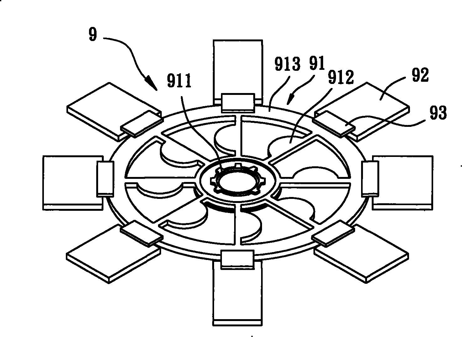
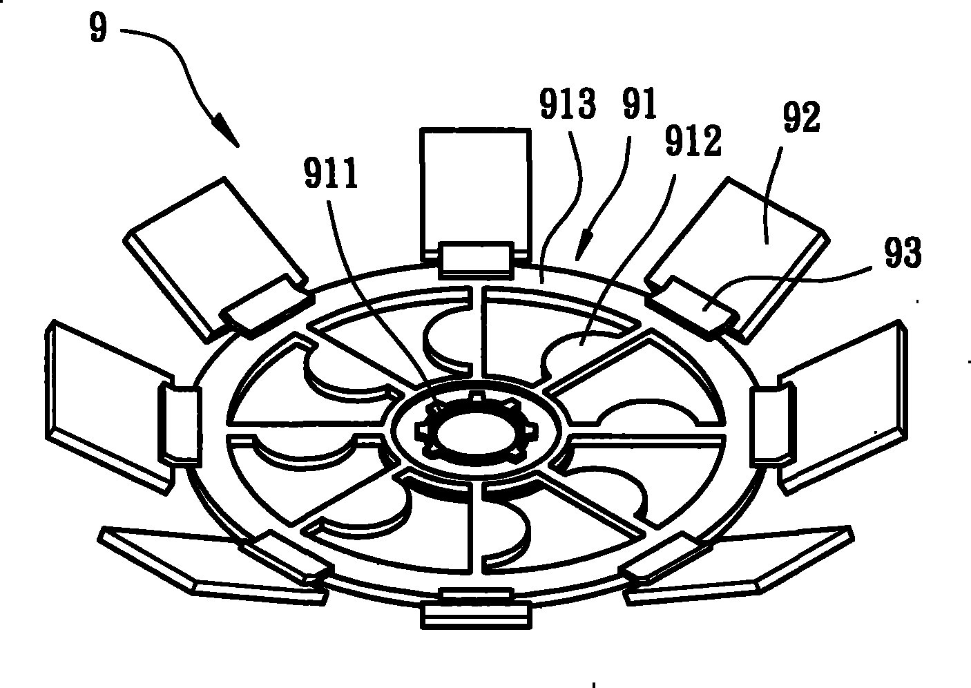
[0050] please refer again image 3 Shown is the self-assembled ultra-micro fan 1 according to the first embodiment of the present invention. The ultra-micro fan 1 includes a body 10 , several blades 20 and several flexible connectors 30 . Wherein the body 10 has a hub 11, the hub 11 is connected to an outer ring 13 with several micro-actuators 12, whereby each of the micro-actuators 12 can be connected between the hub 11 and the outer ring 13, And each of the micro-actuators 12 also has a predetermined distance between each other; each of the blades 20 has a first end 21 and a second end 22, and each of the blades 20 is preferably arranged radially on the body 10 The periphery of the outer ring 13 , the first end 21 of each blade 20 faces the outer ring 13 , and there is a predetermined distance between the first end 21 of each blade 20 and the outer ring 13 .

[0051] The flexible connecting member 30 is selected from a polymer material that can shrink and warp after being h...


PUM


Abstract

The invention relates to a self assembled ultramicro fan, which comprises a body, a plurality of blades and a plurality of flexible connecting pieces. Each blade is mutually connected with the body bythe flexible connecting piece and can take the flexible connecting piece as a pivoting point, and further uses the self assembled technique of a micro electro mechanical system (MEMS) so that each blade can respectively form an angle of inclination opposite to the horizontal direction of the body. In addition, with the help of the structure design of each flexible connecting piece respectively having at least one interconnecting piece or at least one joint portion, each blade can generate more diversified self assembled change of form so as to promote the whole wind dispelling effect of the ultramicro fan.

Description

technical field [0001] The invention relates to a fan, in particular to a self-assembled ultra-micro fan made by miniaturization technology. Background technique [0002] Existing self-assembled ultra-micro fans, as shown in the invention patent No. I275563 "Self-Assembled Structure of Polyimide Film" in Taiwan, China, discloses the self-assembled (Self- assembly) technology made of ultra-micro fan structure. Please refer to figure 1 As shown, the existing micro fan 9 includes a body 91 , several blades 92 and several flexible joints 93 . The body 91 has a hub 911, and the hub 911 is connected to an outer ring 913 with several micro-actuators 912; each of the blades 92 is radially arranged around the outer ring 913 of the body 91; each of the flexible contacts 93 is at one end The blades 92 are respectively connected, and the other end is connected to the outer ring 913 at the same time. [0003] Please refer to figure 2 As shown, the self-assembly (Self-assembly) tech...

Claims


Application Information

Patent Timeline
Patent Type & Authority Patents(China)
IPC IPC(8): F04D29/34B81B5/00F04D29/60
Inventor 洪银树黄义佑李彦其
Owner SUNONWEALTH ELECTRIC MACHINE IND
Why Eureka
Try Eureka