
Oxygen-enriched tiny-oil ignition combustion-stabilizing device

A stable combustion device, micro-oil ignition technology, applied in the direction of combustion ignition, ignition by guiding the flame, combustion method, etc., can solve the problems of unsatisfactory fuel saving effect, complicated use and maintenance, coal slagging and blockage, etc. The effect of wide adaptability, simple structure and convenient maintenance

Active Publication Date: 2009-10-21
CHONGQING FURAN TECH
View PDF0 Cites 13 Cited by
  • Summary
  • Abstract
  • Description
  • Claims
  • Application Information

AI Technical Summary

Problems solved by technology

[0004] First, it is necessary to install a special primary air pulverized coal nozzle for the gasification small oil gun that is matched with the gasification small oil gun, which involves various complicated designs inside the boiler, and the technical risk is high;
[0005] Second, it has poor adaptability to coals with low volatile content such as anthracite, and is highly dependent on coal quality. There is a big gap between theory and practice on the issue of fuel-saving ignition and combustion of different types of coal, and a large amount of oil is still required for lean coal. Combustion-supporting, fuel-saving effect is not ideal;
[0006] Third, due to the staged ignition and combustion, the ignition source with strong rigidity and high temperature generated after fuel gasification is easy to cause coal slagging and blockage at the outlet of the I-stage combustion chamber, which seriously affects the service life of the gasification small oil gun burner. Make it complicated to use and maintain, and the economic cost is higher

Method used


Image

  • Oxygen-enriched tiny-oil ignition combustion-stabilizing device

Examples


Embodiment Construction

[0019] The oxygen-enriched micro-oil ignition and stable combustion device of the present invention will be further described below in conjunction with the accompanying drawings.

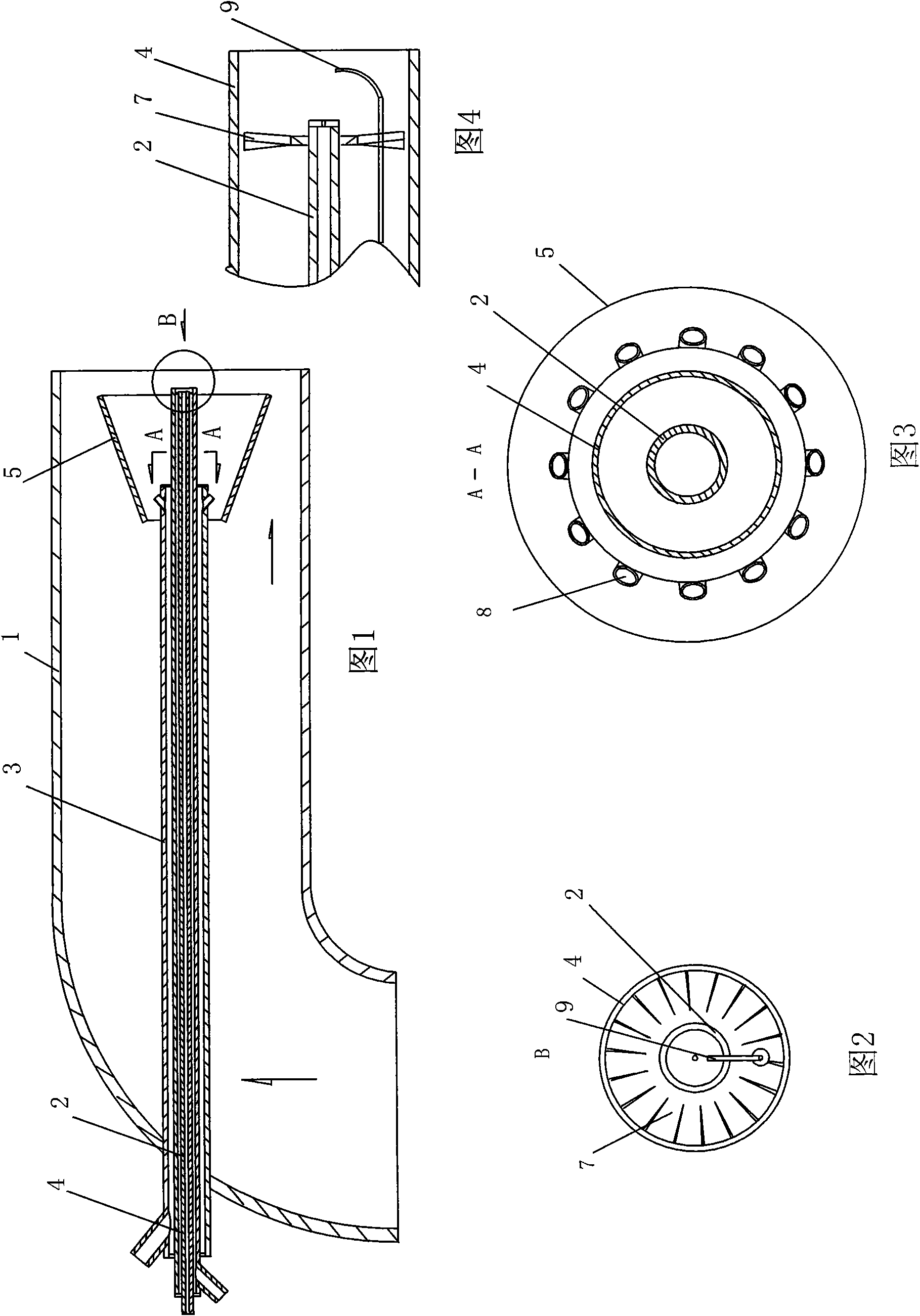
[0020] see Figure 1-Figure 4 , the oxygen-enriched micro-oil ignition and stable combustion device of the present invention includes an ignition fuel conduit 2 with an open right end, and an ignition fuel oxygen conduit 4 coaxial with the ignition fuel oxygen conduit 4 is set at a certain distance outside the ignition fuel conduit 2, and a certain distance is placed outside the ignition fuel oxygen conduit 4 There is a pulverized coal oxygen conduit 3 coaxial with it, and a pulverized coal and oxygen premixing chamber 5 is arranged on the outside of the pulverized coal oxygen conduit 3. The pulverized coal and oxygen premixing chamber 5 is a cone with a small inlet on the left and a large outlet on the right , the right end of the pulverized coal oxygen conduit 3 is located at the left inlet of the...


PUM


Abstract

The invention provides an oxygen-enriched tiny-oil ignition combustion-stabilizing device. The outer side of an ignition fuel duct is sleeved with an ignition-fuel oxygen duct and a pulverized-coal oxygen duct which are coaxial with the ignition fuel duct; the outer side of the pulverized-coal oxygen duct is provided with a chamber for premixing pulverized-coal and oxygen; the chamber for premixing pulverized-coal and oxygen is a cone which is small in a left-side inlet and big in right-side inlet; the right end of the pulverized-coal oxygen duct is positioned on the left-side inlet of the chamber for premixing pulverized-coal and oxygen; the right end of the ignition-fuel oxygen duct is positioned on the right-side inlet of the chamber for premixing pulverized-coal and oxygen; a right-end outlet of the ignition-fuel oxygen duct and an ignition head of an igniter are positioned on the right side of a right-end outlet of the ignition fuel duct; a right-end outlet of the pulverized-coal oxygen duct is sealed; a plurality of gas orifices surrounding the pulverized-coal oxygen duct are arranged near the right-end outlet of the pulverized-coal oxygen duct; and the gas orifices and the pulverized-coal oxygen duct are at an included angle of greater than 45 degrees and less than 90 degrees in the axial direction. The oxygen-enriched tiny-oil ignition combustion-stabilizing device has the advantages of simple structure, little technical risk, extensive coal applicability, convenient maintenance and low cost.

Description

technical field [0001] The invention relates to a power station boiler using primary air pulverized coal as fuel, in particular to an oxygen-enriched micro-oil ignition and stable combustion device. Background technique [0002] Power plant boilers fueled by primary air pulverized coal are the main force of thermal power generation in my country. Due to the great differences in coal quality in different production areas in my country, a large amount of combustion oil is required to start and stop power generation boilers and stabilize combustion at low loads. In order to save costs and reduce fuel consumption, a considerable number of small oil (gas) ignition and stable combustion technologies for power plant boilers have been developed in my country. The gasification small oil gun ignition and stable combustion technology is one of the representatives and has been widely used. [0003] However, due to the combustion mechanism of the gasification small oil gun micro-oil igni...

Claims


Application Information

Patent Timeline
IPC IPC(8): F23Q9/00
CPCY02E20/34
Inventor 向卫王庆薛勤普杜毅任友华
Owner CHONGQING FURAN TECH
Learn More