Cable connector plug

A cable connection and plug technology, which is applied in the direction of conductive connection, connection, clamping/spring connection, etc., can solve the problem of cable shortening, and achieve the effect of low cost

Active Publication Date: 2009-10-21
PHOENIX CONTACT GMBH & CO KG
View PDF3 Cites 9 Cited by
  • Summary
  • Abstract
  • Description
  • Claims
  • Application Information

AI Technical Summary

Problems solved by technology

If the ends of the individual cores which have already been cut off by the cutting terminal have to be cut off when...

Method used


Image

  • Cable connector plug
  • Cable connector plug
  • Cable connector plug

Examples


Embodiment Construction

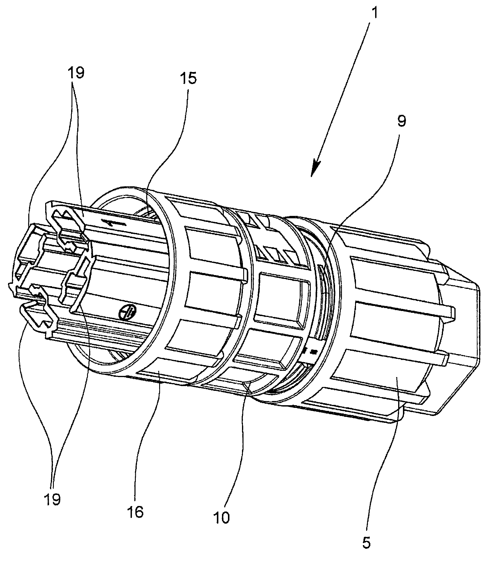
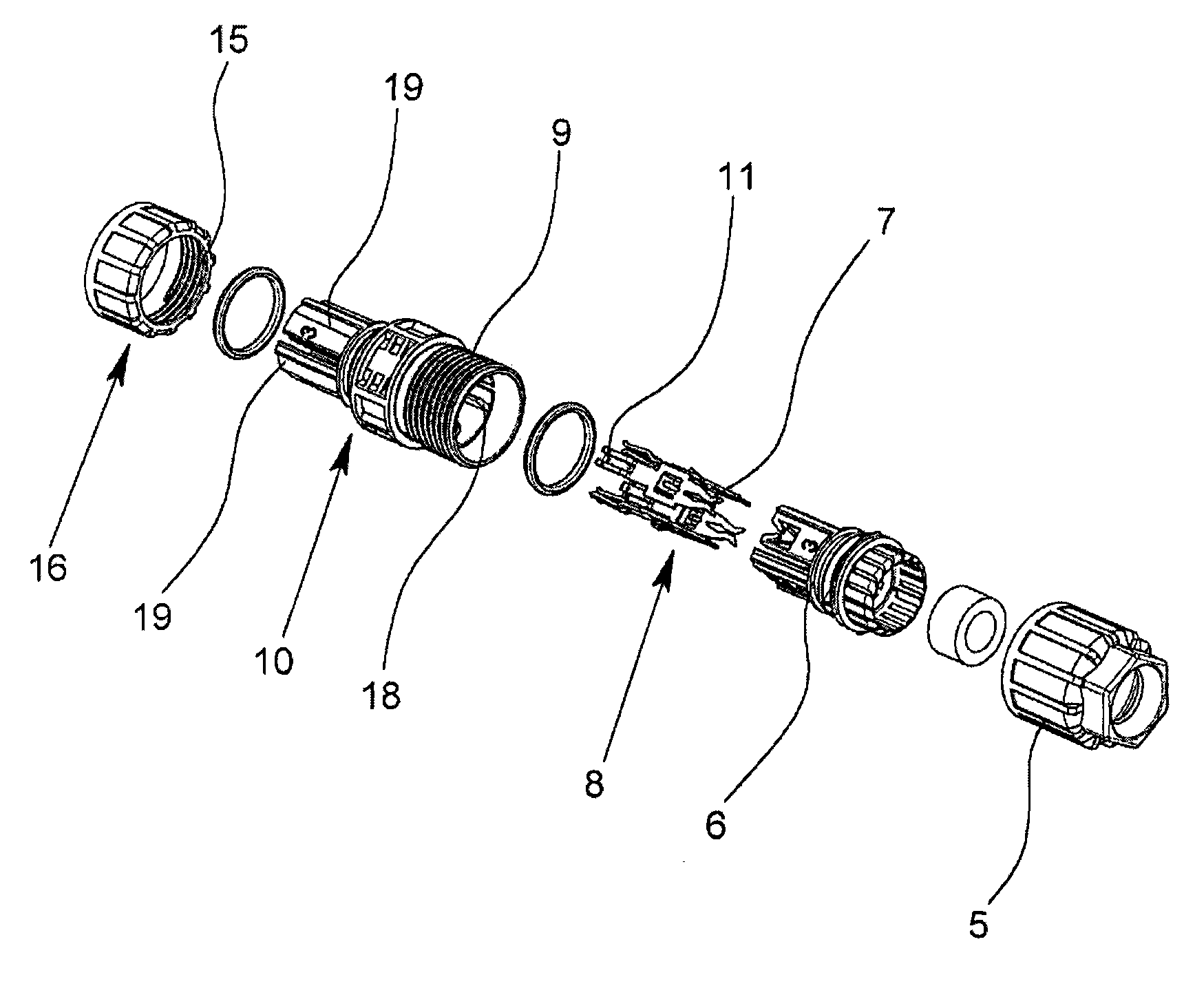
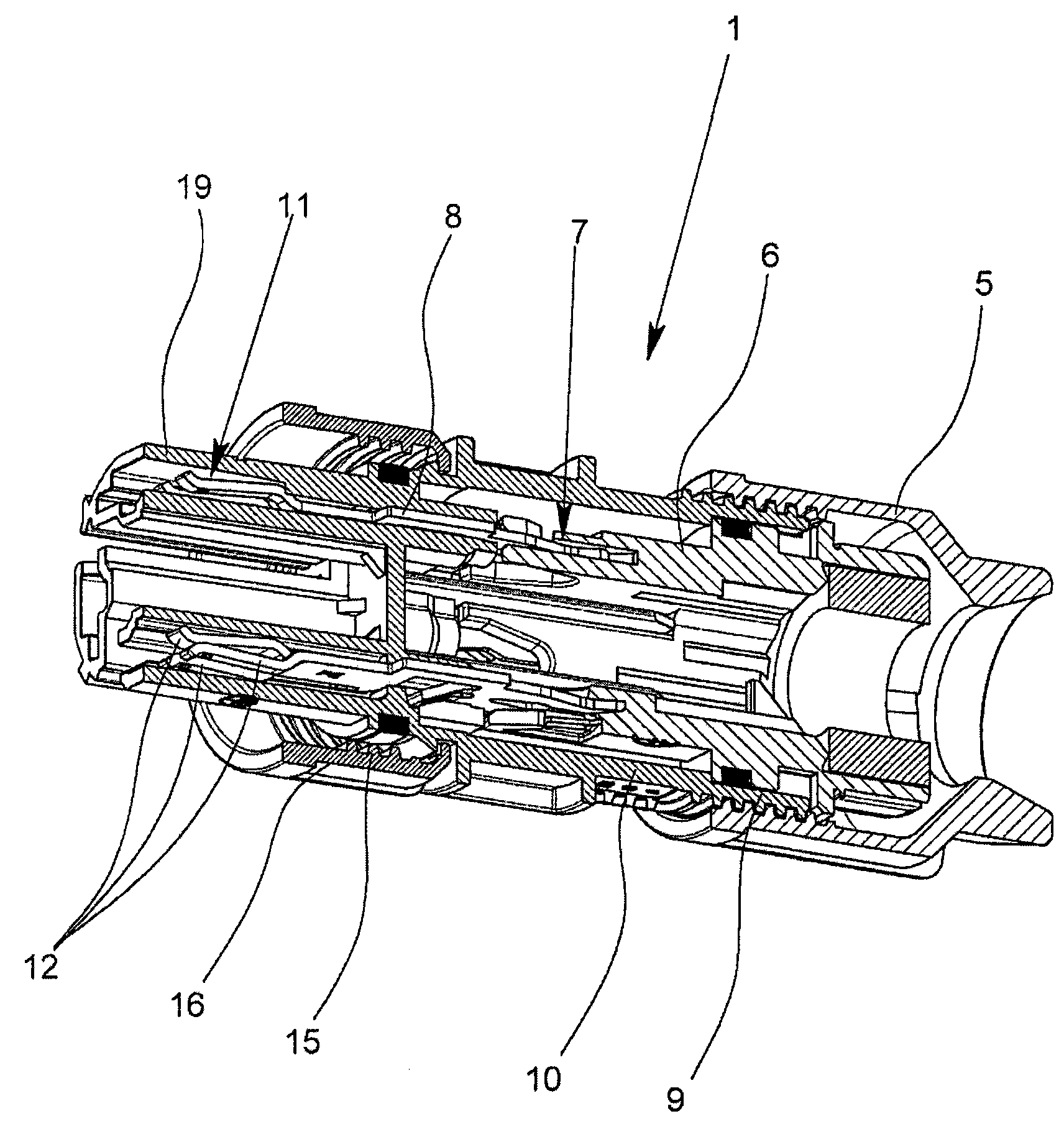
[0032] Figures 1 to 3 shows a socket for connecting a quad cable not shown here to the Figure 4 Cable connection plug 1 on connection device 3 with cut terminal 2 of electrical distributor 4 shown in .

[0033] The cable connection plug 1 comprises in particular a union nut 5, a conductor receiving and guiding element 6, four contact elements 8 each having a cut-off terminal 7 on their side facing the cable to be connected, and one having and The internal thread of the locking nut corresponds to the connecting body 10 of the external thread 9 . To connect a cable to the cable connection plug 1 , the union nut 5 is first pushed onto the end of the cable from which the cable insulation has been removed. The individual cores are then inserted into the core guides of the core receiving and guiding element 6 in order to press the cores into the cut terminal when screwing the union nut onto the connecting body 10 7, whereby the cutting terminal 7 cuts the insulating layer of th...


PUM


Abstract

The present invention relates to a cable connector plug used for connecting multi-core cable to a connection device having a plurality of cutting terminals of an electric distributor, the plug has a locking nut, a core receiver having a plurality of core guide grooves, and a guide member, multiple contact elements provided with an insulation displacement terminal and a connection element contact spring and a capsule-shaped connection body having external threads that correspond to an internal thread of an union nut, wherein the cutting terminal cuts core insulation layer plugged into the coreterminal in the core guide groove to contact with wire of the cable when the locking nut is locked on the connector, and the spring element is contact spring, which has two spring legs lying oppositeto each other. The spring legs contact individual insulation displacement terminals on flat sides lying opposite to each other during connection of plug with a connection device.

Description

technical field [0001] The invention relates to a cable connection plug for connecting a multi-core cable to a connection device with cut terminals of an electrical distributor. Furthermore, the invention relates to an electrical distributor for distributing electric current. Background technique [0002] From DE 101 39 202 B4 there is known an electrical distributor for distributing electric current, which has a housing with a plurality of connection devices, wherein the individual connection devices each have a circular ring with an external thread on the connection side A cylindrical threaded flange, and a plurality of connecting elements configured as cutting terminals are respectively arranged in the connecting device. The cut terminals of the individual connecting devices are electrically connected to one another by means of connecting elements. According to one specific embodiment, the connecting element is designed here as a busbar, wherein the cut-off terminal ass...

Claims


Application Information

Patent Timeline
IPC IPC(8): H01R4/24H01R4/48H01R9/03
CPCH01R13/405H01R13/41H01R9/031H01R13/44H01R4/2433H01R13/112H01R13/622
Inventor J·格鲁利斯
Owner PHOENIX CONTACT GMBH & CO KG
Why Eureka
Try Eureka