Single-phase reluctance generator

A reluctance generator, single-phase technology, applied to synchronous motors with static armatures and rotating magnets, synchronous machine parts, magnetic circuit rotating parts, etc., can solve the problem that permanent magnet rotors cannot use claw-pole rotors, Increase the manufacturing cost, operating cost, one-way current in the power generation state, etc., to achieve the effect of improving efficiency, reducing equipment cost, and increasing power density

Inactive Publication Date: 2009-10-21
张世清
View PDF1 Cites 15 Cited by
  • Summary
  • Abstract
  • Description
  • Claims
  • Application Information

AI Technical Summary

Problems solved by technology

However, the switched reluctance motor (SRM) in the prior art is mechanically driven and in the state of switched reluctance generator (SRG for short), the excitation is unidirectional controllable and time-sharing, while the power generation is unidirectional and time-sharing uncontrollable. , and the current in the power generation state is also unidirectional; more importantly, the original switched reluctance motor SRM is converted to the switched reluctance generator SRG state, and the output is DC power instead of AC power
[0003] Due to the difference in the pole structure of the double salient pole of the switched reluctance motor, that is, the stator and rotor poles are not equal, the number of stator poles is greater than the number of rotor poles, and in the power generation state, the switch tube is also required to control the excitation current of the stator winding and the time for controlling its excitation control angle. , which increases the manufacturing cost and operating cost by 1 / 3-2 / 5, and the excitation method is a phase-separated and stage-by-stage excitation method, which means that the control of the switched reluctance motor is more complicated in the reversible state as a power generation operation. When the motor rotates once, the power tube is electronically controlled for phase-separated excitation and time-sharing for alternate excitation and phase-separated power generation. If the control is good, at most two-phase power generation, because the excitation takes a certain amount of time, it affects the power generation efficiency.
[0004] The patent name I have applied for is "Switched Reluctance Motor Generator", and the invention patent with the patent application number 200810017433.2 is completely different from the invention patent technology I am applying for now. The applied invention technology is electronically controlled when the rotor is not excited. The stator winding is energized to generate a rotating magnetic field and used as a motor. Under the action of the mechanically driven rotating force, the electrical energy output is generated through excitation, and the number of stator and rotor poles is not equal. The number of rotor poles is less than the number of stator poles. It can be composed of different phases and different poles. , the rotor can only be composed of a magnetic pole rotor with windings, and cannot use the stator and rotor equal pole technology, nor can it use the permanent magnet rotor, let alone the claw pole rotor, and the control technology is more complicated. The switched reluctance motor is mechanically driven on the rotor. In the case of a field winding, it becomes a generator

Method used


Image

  • Single-phase reluctance generator
  • Single-phase reluctance generator
  • Single-phase reluctance generator

Examples


Embodiment 1

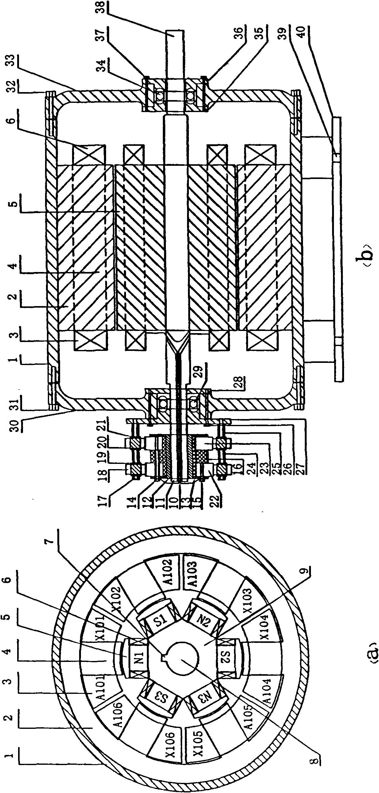
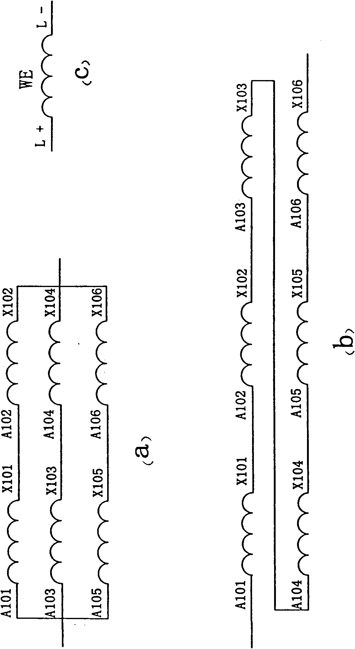
[0039] Such as figure 1 a, b and image 3 , Figure 5 As shown: the single-phase magnetic group generator consists of a stator and a rotor, both of which are laminated with silicon steel sheets to form a salient pole structure; the stator part includes the stator shell 1, the stator yoke 2, the stator armature winding 3, the stator pole 4 and the base 40, etc., the rotor part includes the rotor pole 5, the rotor field winding 6, the rotor yoke 9, the rotor shaft 11, and the front and rear bearings 29, 34, etc.; there are concentrated armature windings on the salient poles of the stator, and the windings are based on the N and S of the armature windings. The polarities are connected in series or in parallel to form a phase. Armature windings 3 are sheathed on the salient magnetic poles of the stator, and the armature windings on two adjacent salient poles of the winding 3 are connected in anti-phase series to form a set of windings, while the rotor windings are connected in a...

Embodiment 2

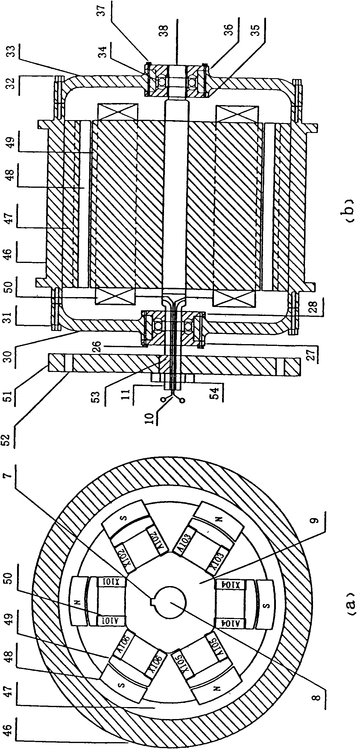
[0044] Such as figure 2 As shown in a and b: it is a single-phase 6 / 6 double-salient electric excitation type equal-pole outer rotor generator; the technology adopted is to change the rotor to a permanent magnet outer rotor, that is, neither the inner stator nor the outer rotor need to slide Ring (non-excitation), the shell 46 of the motor is a rotating shell or a rotating pulley; this technology only changes the electric excitation winding of the rotor into a permanent magnet outer rotor; its principle and application are the same as figure 1 The same; the stator armature series is the same image 3 b, parallel connection with image 3 a.

Embodiment 3

[0046] Such as Figure 4 As shown in a and b: it is a single-phase 8 / 8 double salient pole permanent magnet type equal pole inner rotor permanent magnet generator; the technology used is the outer stator inner rotor, which increases the number of poles (adding two more poles); the inner rotor magnet A permanent magnet pole 41 is fixed on the yoke 9, where the permanent magnet pole rotor does not need a slip ring. Its stator armature winding is 4-way or 2-way parallel connection can reduce the output voltage and increase the output current, 1-way series connection can increase the output voltage, and the output current is equal to the rated current of the winding.


PUM


Abstract

The invention discloses a single-phase reluctance generator which comprises a stator and a rotor in projecting magnetic pole structures by stacking silicon-steel sheets. Stator magnetic poles are provided with concentrated armature windings which are connected in series or parallel into a group according to the N polarity and the S polarity of the armature windings; rotary magnetic poles arranged on the rotor has the same number as the magnetic pole number of the stator and comprise winding excitation magnetic poles or permanent-magnet magnetic poles and permanent-magnet excitation mixed magnetic poles; magnetic pole windings adjacent to the rotor are connected in series or parallel to form a plurality of N groups and S groups; and the stator poles and the rotor poles consist of 2-stage poles, 4-stage poles, or even n-stage poles, namely even poles or pair poles, respectively comprise different stage poles and have the same total pair poles. The invention adopts a stator isopolar technology so that the rotor can adopt different modes, such as the excitation magnetic poles, the permanent-magnet magnetic poles and the mixed magnetic poles of the permanent-magnet magnetic poles and the electric excitation magnetic poles, and the stator windings can be simultaneously utilized; the dynamic combination of the windings connected in series or parallel facilitates the adjustment of an output voltage, improves the utilization rate of the windings, enhances the power density of the generator and improves the performance and the efficiency of the generator.

Description

technical field [0001] The invention belongs to the technical field of generators, in particular to a single-phase reluctance generator. Background technique [0002] The existing switched reluctance motor (SRM) is a motor with a double salient pole structure. Its stator and rotor are both salient poles and are made of laminated ordinary silicon steel sheets. Concentrated windings are wound on the stator poles, and the rotor is both There are no windings and no permanent magnets; the motor can be divided into single-phase, two-phase, three-phase, four-phase and multi-phase switched reluctance motors according to the number of phases, and the three-phase 6 / 4 pole structure, 12 / 8 pole structure and Four-phase 8 / 6-pole structures are mostly; the advantages of switched reluctance motors are: simple structure, easy to manufacture, high operating efficiency, high power factor, small starting current, large starting torque, strong overload capacity, and wide speed range All have h...

Claims


Application Information

Patent Timeline
Patent Type & Authority Applications(China)
IPC IPC(8): H02K21/02H02K21/12H02K1/27H02K3/04
Inventor 张世清张红梅
Owner 张世清
Why Eureka
Try Eureka