Crystal device for surface mounting

A surface mount, crystal technology, used in electric solid devices, semiconductor devices, electrical components, etc., can solve problems such as poor bonding, electrode roller speed changes, current fluctuations, etc., to improve productivity, increase allowable range, and increase welding efficiency. Effect

Active Publication Date: 2009-10-21
NIHON DEMPA KOGYO CO LTD
View PDF10 Cites 4 Cited by
  • Summary
  • Abstract
  • Description
  • Claims
  • Application Information

AI Technical Summary

Problems solved by technology

As a result, current fluctuations, etc. are generated, and even if the current value is strictly limited, the speed change of the electrode roller will actually occur.
Therefore, poor bonding is increased, and the productivity of surface mount units may be reduced
[0017] Because the mounting unit is made smaller, for example, as mentioned above, its planar profile is 2.0×1.6mm or less, these problems become more prominent, the width of the metal ring 4 is made narrower, and the sealing path L (with The joint width of the metal cover 3) is also narrower to limit its welding conditions

Method used


Image

  • Crystal device for surface mounting
  • Crystal device for surface mounting
  • Crystal device for surface mounting

Examples


Embodiment Construction

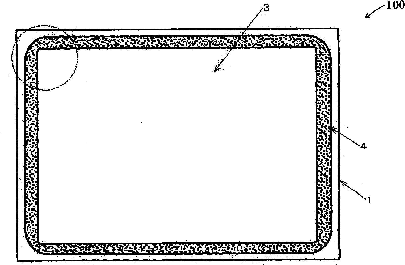
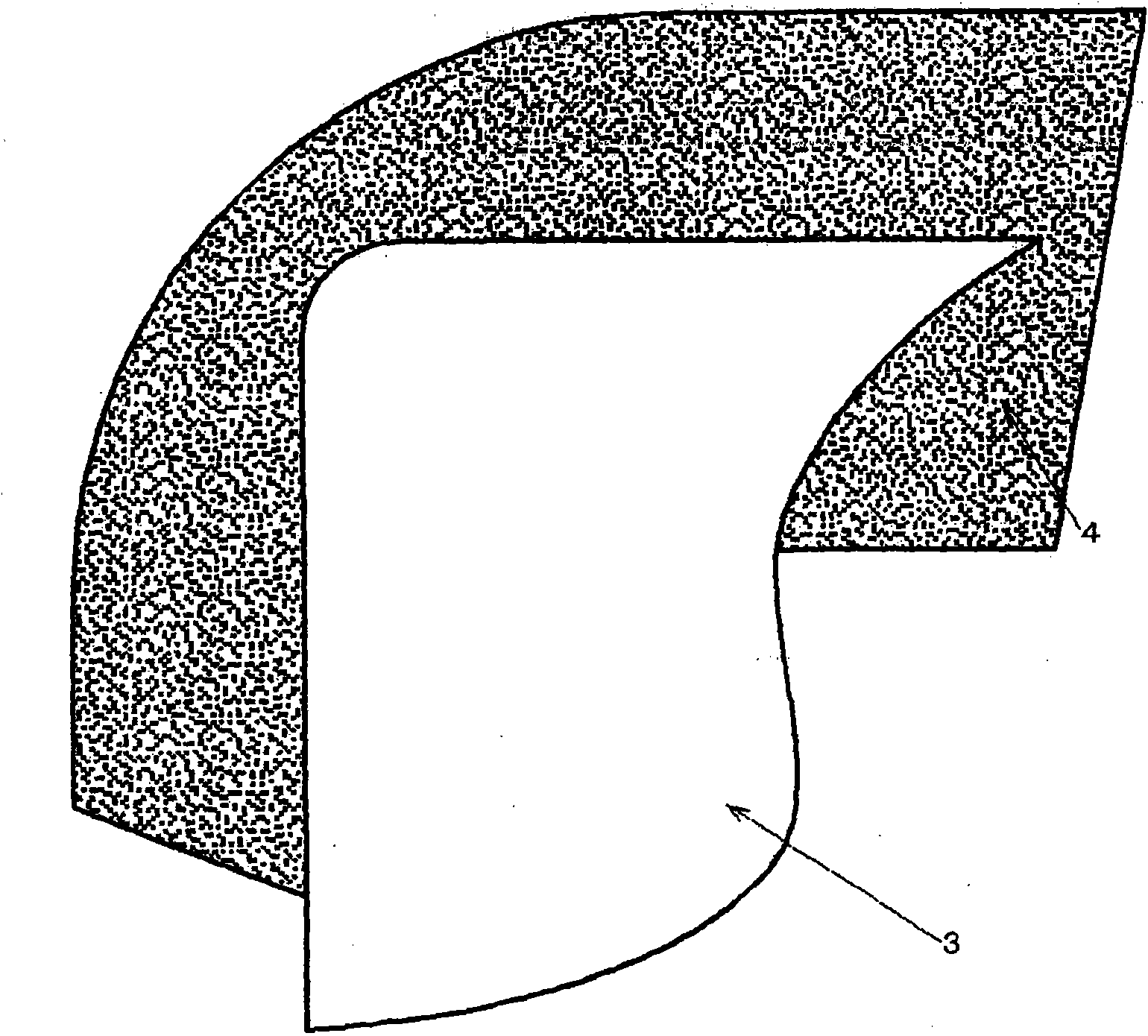
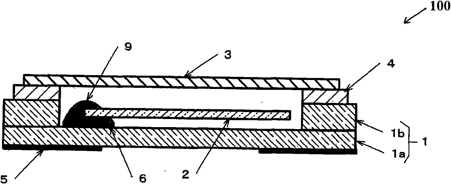
[0030] Figure 1A to Figure 2B is a schematic diagram of a surface mount unit used to illustrate an embodiment of the present invention, where Figure 1A is a plan view of the surface mount unit with the metal cover engaged, Figure 1B yes Figure 1A The magnified view of the part indicated by the O-shaped dashed line in , Figure 1C is a cross-sectional view of the surface mount unit, Figure 2A is the plan view of the ferrule of the surface mount unit, and Figure 2B It is a floor plan of the metal cap. Incidentally, the same parts as those in the related art are denoted by the same symbols, and their descriptions are simplified or omitted.

[0031] The surface mount unit 100 according to the present invention is constructed such that the crystal element 2 is housed in the ceramic case 1, and the metal cover 3 is bonded to the metal ring 4 which is provided on the end face of the opening by seam welding so as to be airtight Package the crystal element 2 . The ceramic ...


PUM


Abstract

A crystal device for surface mounting, in which a metal cover is jointed to the metal ring by seam welding, satisfies relationships A2 / A1<C2 / C1 and B2 / B1<D2 / D1, where A1 is a length of a long side of the metal ring, A2 is a length of a straight portion of a long side except for curved portions, B1 is a length of a short side of the metal ring, B2 is a length of a straight portion of the short sideexcept for the curved portions thereof, C1 is a length of a long side of the metal cover, C2 is a length of a straight portion of the long side except for the curved portions thereof, D1 is a lengthof a short side of the metal cover, and D2 is a length of a straight portion of the short side except for the curved portions thereof.

Description

[0001] This application claims priority from Japanese Patent Application No. 2008-107108 filed on Apr. 16, 2008, the entire subject matter of which is hereby incorporated by reference. technical field [0002] The invention relates to the technical field of surface-mounted crystal devices suitable for miniaturization, in particular to a crystal device in which a crystal element is hermetically packaged by seam welding. Background technique [0003] Crystal devices for surface mounting such as crystal units, crystal oscillators or crystal filters are commonly referred to as frequency control components. For example, a crystal unit for surface mounting (hereinafter, referred to as a surface mounting unit) is incorporated into an oscillator circuit to be installed in various types of electronic equipment as a frequency source or a time reference. In recent years, further progress has been made in its miniaturization, so that its planar profile is, for example, 2.0×1.6 mm or sma...

Claims


Application Information

Patent Timeline
Patent Type & Authority Applications(China)
IPC IPC(8): H03H9/05
CPCH03H9/0547H03H9/1021H01L2924/16195
Inventor 村濑重善石丸千里
Owner NIHON DEMPA KOGYO CO LTD
Why Eureka
Try Eureka