Continuous compensating method of displacement precision of digital controlled shaft of digital controlled machine tool

A technology of numerical control machine tools and compensation methods, which is applied in the direction of automatic control devices, metal processing machinery parts, feeding devices, etc., and can solve the problems of difficulty in restoring the accuracy of machine tools, errors, unfavorable maintenance of machine tools, etc.

Inactive Publication Date: 2009-10-28
贵州科邦科技实业有限责任公司
View PDF0 Cites 18 Cited by
  • Summary
  • Abstract
  • Description
  • Claims
  • Application Information

AI Technical Summary

Problems solved by technology

[0005] 1. This compensation method only considers the error between the end point and the starting point, but does not consider the error between the starting point and the end point (for example, when running to points B, C, D, E, and F, these points are relatively The error of the starting point), without continuous compensation for the CNC axis, according to the interpolation principle of CNC machine tool trajectory processing, these errors will lead to relatively large processing trajectory errors
[0006] 2. If the "positioning accuracy" of the CNC axis is required to be high, denser points must be selected for testing (for example, some CNC systems require the number of test points for a single axis to reach thousands of points), which is difficult in actual use. Especially when the machine tool user wants to restore the accuracy of the machine tool, it is more difficult
[0007] 3. Test the CNC axis of any CNC machine tool. The mechanical clearance value is not the same value at each point (o

Method used

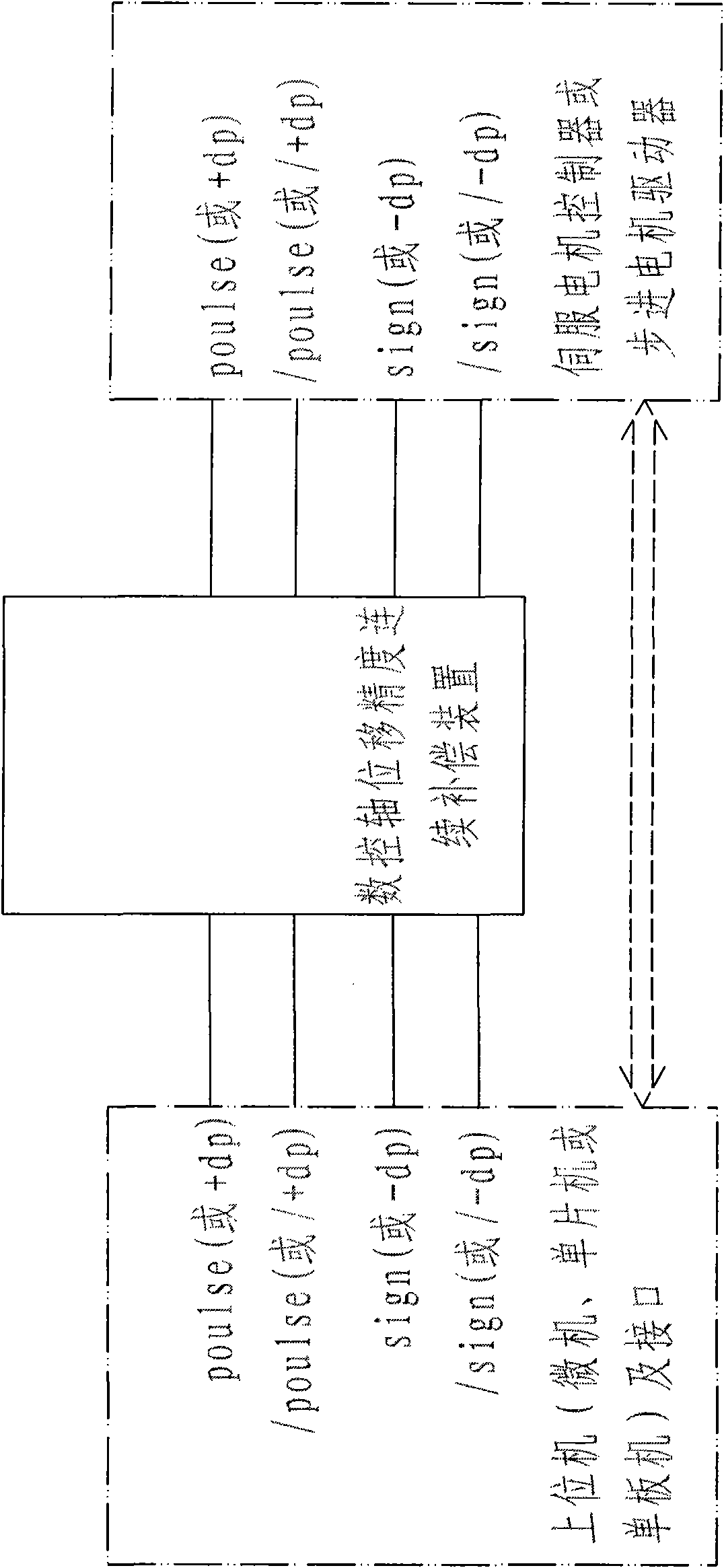

Image

  • Continuous compensating method of displacement precision of digital controlled shaft of digital controlled machine tool
  • Continuous compensating method of displacement precision of digital controlled shaft of digital controlled machine tool
  • Continuous compensating method of displacement precision of digital controlled shaft of digital controlled machine tool

Examples


Embodiment Construction

[0062] Below in conjunction with the accompanying drawings and preferred embodiments, the specific implementation, structure, features and effects of a method for continuously compensating the displacement accuracy of the numerical control axis of a numerical control machine tool according to the present invention will be described in detail as follows.

[0063] A method for continuously compensating the displacement accuracy of a numerical control axis of a numerical control machine tool, comprising the following steps:

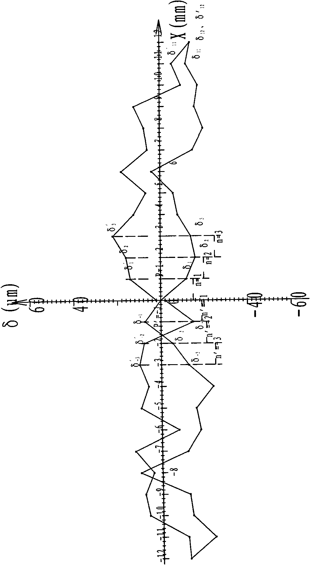
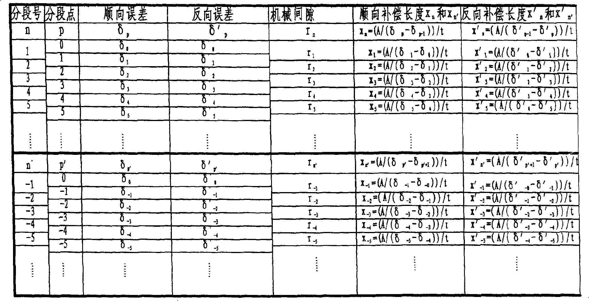
[0064] (1) Set a reference point 0 at the middle position within the effective stroke range of the CNC axis, divide the effective stroke of the CNC axis into a number of equal line segments with a length of A with the reference point as the origin, and divide the effective stroke of the CNC axis into For positive segmentation and negative segmentation, the positive segmentation point is marked as p (p=1, 2, 3, 4, 5, ...); the negative segmentation point is ma...


PUM


Abstract

The invention discloses a continuous compensating method of the displacement precision of a digital controlled shaft of a digital controlled machine tool. The effective stroke of a digital controlled shaft is divided into a plurality of equal segments with A length by taking a reference point as an original point, the reference point is used as the boundary for dividing the effective stroke into positive sections and negative sections, the point of the positive sections is marked as p, the point of the negative sections is marked as p', the number of the positive sections is marked as n, and the number of the negative sections is marked as n'. The running of the digital controlled shaft along the direction leaving the reference point is defined as consequent running, and the running of the digital controlled shaft along the direction close to the reference point is defined as reversed running. The reference point is used as a starting point, and a laser interferometer is used for measuring the consequent and reversed error values delta p and delta p' of every section point of the digital controlled shaft corresponding to the reference point, and the displacement-error curve of the digital controlled shaft is acquired. The consequent and reversed error linear functions of every section are respectively established according to the measuring result. Unit conversion, data list preparation and compensation are respectively carried out. The continuous compensating method of displacement precision of the digital controlled shaft of the digital controlled machine tool can realize the positioning precision compensation of the digital controlled shaft, the error compensation of the moving track of the digital controlled machine tool and the section gap compensation of the digital controlled shaft.

Description

technical field [0001] The invention relates to a continuous compensation method for the displacement accuracy of a numerical control axis of a numerical control machine tool. Background technique [0002] In the CNC machine tool, the position control of a certain CNC axis (or coordinate axis) is controlled by the direction signal plus the walking pulse signal or the positive direction walking pulse signal plus the negative direction walking pulse signal, no matter which method is used , the results are the same, that is, whenever the servo controller or stepping motor driver receives a walking pulse signal from the host computer, it will make the servo motor or stepping motor rotate a fixed angle, and then pass through the transmission chain (connected Axis device, reducer, screw nut pair, etc.) to convert the motor rotation angle into a fixed displacement of the CNC axis—pulse equivalent (expressed in t), and the direction signal can make the CNC axis follow the instructio...

Claims


Application Information

Patent Timeline
IPC IPC(8): B23Q23/00B23Q15/00
Inventor 杨润生郭宇航张宏斌
Owner 贵州科邦科技实业有限责任公司
Why Eureka
Try Eureka