Supercharge Your Innovation With Domain-Expert AI Agents!

Method for grinding inner hole of front segment camshaft by external grinding machine

A cylindrical grinding machine, camshaft technology, applied in grinding machines, grinding/polishing equipment, machine tools designed for grinding the rotating surface of workpieces, etc. Large and other problems, to achieve the effect of convenient clamping, reduced labor intensity, and firm clamping

Inactive Publication Date: 2009-10-28
SHENGLI OIL FIELD SHENGLI POWER MACHINERY GRP
View PDF0 Cites 7 Cited by
  • Summary
  • Abstract
  • Description
  • Claims
  • Application Information

AI Technical Summary

Problems solved by technology

Although this structure can also complete the processing of the inner hole, it also has the following disadvantages or deficiencies: ①Due to the positioning and clamping error between the three-jaw chuck and the spindle headstock of the grinding machine, the jump at this place becomes larger, resulting in grinding The axis of the rear inner hole is not on the same line as the centerline of the shaft
②Because the chuck in the process of grinding the inner hole of the front section of the camshaft holds the outer circle of the spline, and after the grinding of the front section of the manhole is completed, it must be assembled with the rear section, resulting in the spline of the entire wheel shaft being inspected next week. The runout of the center circle becomes larger (the circle of the spline has been finely ground to the finished size before grinding the inner hole)
③ The runout of the peach-shaped base circle near the joint of the inner hole becomes larger, which seriously affects the quality and use effect of the camshaft

Method used


Image

  • Method for grinding inner hole of front segment camshaft by external grinding machine
  • Method for grinding inner hole of front segment camshaft by external grinding machine
  • Method for grinding inner hole of front segment camshaft by external grinding machine

Examples


Embodiment Construction

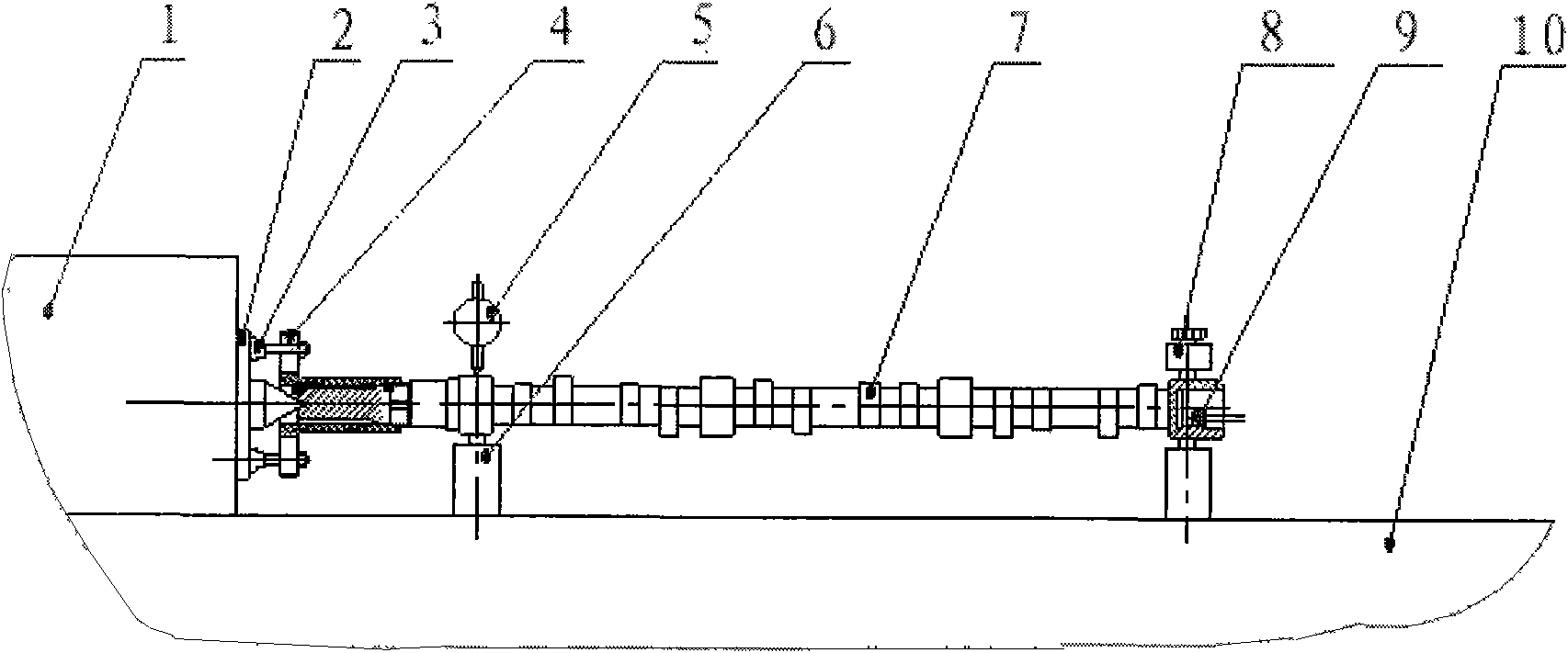
[0014] refer to Figure 1-Figure 3 , a method for cutting the inner hole of a front camshaft with an outer cylindrical grinder, comprising the use of an outer cylindrical grinder and an inner hole grinding tool. The headstock 1 of the grinding machine, the pulling disc 2 and the top of the headstock 1 of the grinding machine are in close contact with the center hole of the front section of the camshaft 7, so that the design datum, measurement datum and machining datum of the front section of the camshaft 7 coincide.

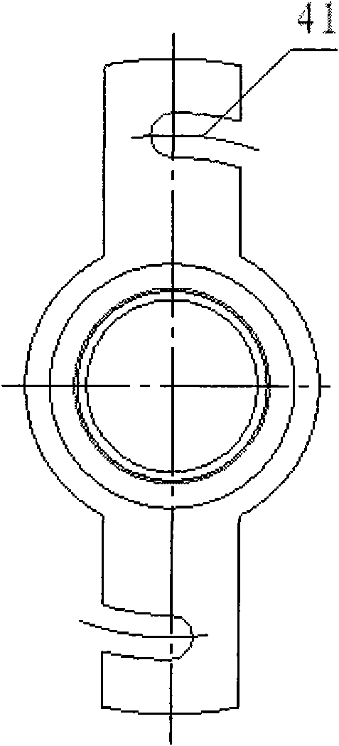
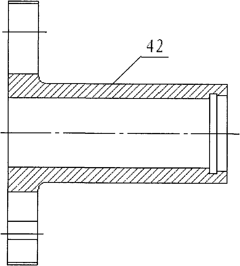
[0015] The camshaft 7 inner hole grinding tool 4 adopts the connection mode of the double U-shaped groove 41 and the grinding machine headstock 1. The camshaft 7 inner hole grinding tool 4 is connected with the front camshaft by M52×1.5 internal thread, and is axially tensioned with the camshaft 7 . The inner hole grinding tool 4 is a tubular structure with a connecting arm at one end, and the tubular body 42 is provided with an M52×1.5 internal screw. Both sid...


PUM


Abstract

The invention provides a method for grinding an inner hole of a front segment camshaft by an external grinding machine, which uses an external grinding machine and inner hole grinding tool. The method is characterized in that: a head holder driver chuck of the grinding machine and a head holder core clamper of the grinding machine are closely contacted with a central hole of a front segment of the camshaft to make design basis, measurement basis and processing basis of the front segment of the camshaft coincident. The method can make the design basis, measurement basis and processing basis of the front segment of the camshaft coincident, so that the circular run-out on a spline and the axiality of the ground inner hole of the front segment of the camshaft and the shaft are ensured strictly, and the peach-shaped basic circle run-out value strictly conforms to the single segment parameter value after the camshaft is assembled. Moreover, the method also has the characteristics of simple structure, easy operation, high working efficiency, and stable quality, and is widely applied to grinding processing of the inner hole of the front segment of the camshaft by the external grinding machine.

Description

1. Technical field [0001] The invention relates to an outer cylindrical grinder, in particular to a method for cutting the inner hole of a front camshaft by an outer cylindrical grinder. 2. Background technology [0002] The camshaft is the key component of the engine. The camshaft of the 190 gas engine is a slender part. The traditional grinding process of the inner hole on the slender shaft is to clamp the outer circle with a chuck at one end of the shaft at the decorative frame of the grinder, and clamp the outer circle at the other end. Mounted on a three-point stand to complete. Although this structure can also complete the processing of the inner hole, it also has the following disadvantages or deficiencies: ①Due to the positioning and clamping error between the three-jaw chuck and the spindle headstock of the grinding machine, the jump at this place becomes larger, resulting in grinding The axis of the rear inner hole is not on the same straight line as the centerlin...

Claims


Application Information

Patent Timeline
Patent Type & Authority Applications(China)
IPC IPC(8): B24B5/48
Inventor 宗军成胜许金云徐蕊
Owner SHENGLI OIL FIELD SHENGLI POWER MACHINERY GRP
Features
  • R&D
  • Intellectual Property
  • Life Sciences
  • Materials
  • Tech Scout
  • Unparalleled Data Quality
  • Higher Quality Content
  • 60% Fewer Hallucinations
Learn More