High temperature air source heat pump hot-air fan used for drying

An air source heat pump, high temperature air technology, used in drying gas layout, dryer, drying and other directions, can solve the problems of low heating temperature, unable to meet the requirements of drying, overpressure protection shutdown, etc., to reduce the intake pressure , Simple and easy design, stable pressure reduction effect

Inactive Publication Date: 2009-10-28
湖南省浏阳市择明热工器材有限公司
View PDF0 Cites 16 Cited by
  • Summary
  • Abstract
  • Description
  • Claims
  • Application Information

AI Technical Summary

Problems solved by technology

[0007] The heat exchange area of ​​the evaporator of the existing device is small, the heat energy absorbed from the environment is limited, and it cannot provide the heat and temperature required for drying materials
[0008] 2. The ability to output heat energy is limited and the heating temperature is low:
[0009] The heat transfer area of ​​the condenser used in the existing device is small, resulting in limited heat carrying capacity and heat transfer capacity of the condenser, and low heat transfer efficiency
When the ambient temperature is high, the absorbed heat cannot be output in a timely and effective manner, which instead causes the internal temperature and pressure of the working medium circulation system to be too high, the compressor runs continuously under high pressure, frequent over-pressure protection stops,

Method used


Image

  • High temperature air source heat pump hot-air fan used for drying
  • High temperature air source heat pump hot-air fan used for drying
  • High temperature air source heat pump hot-air fan used for drying

Examples


Embodiment Construction

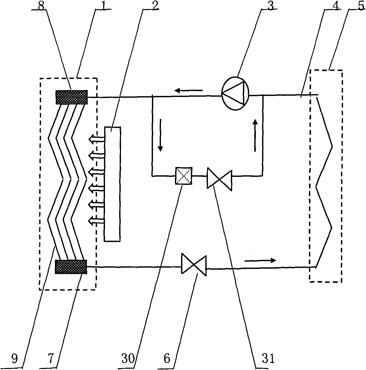
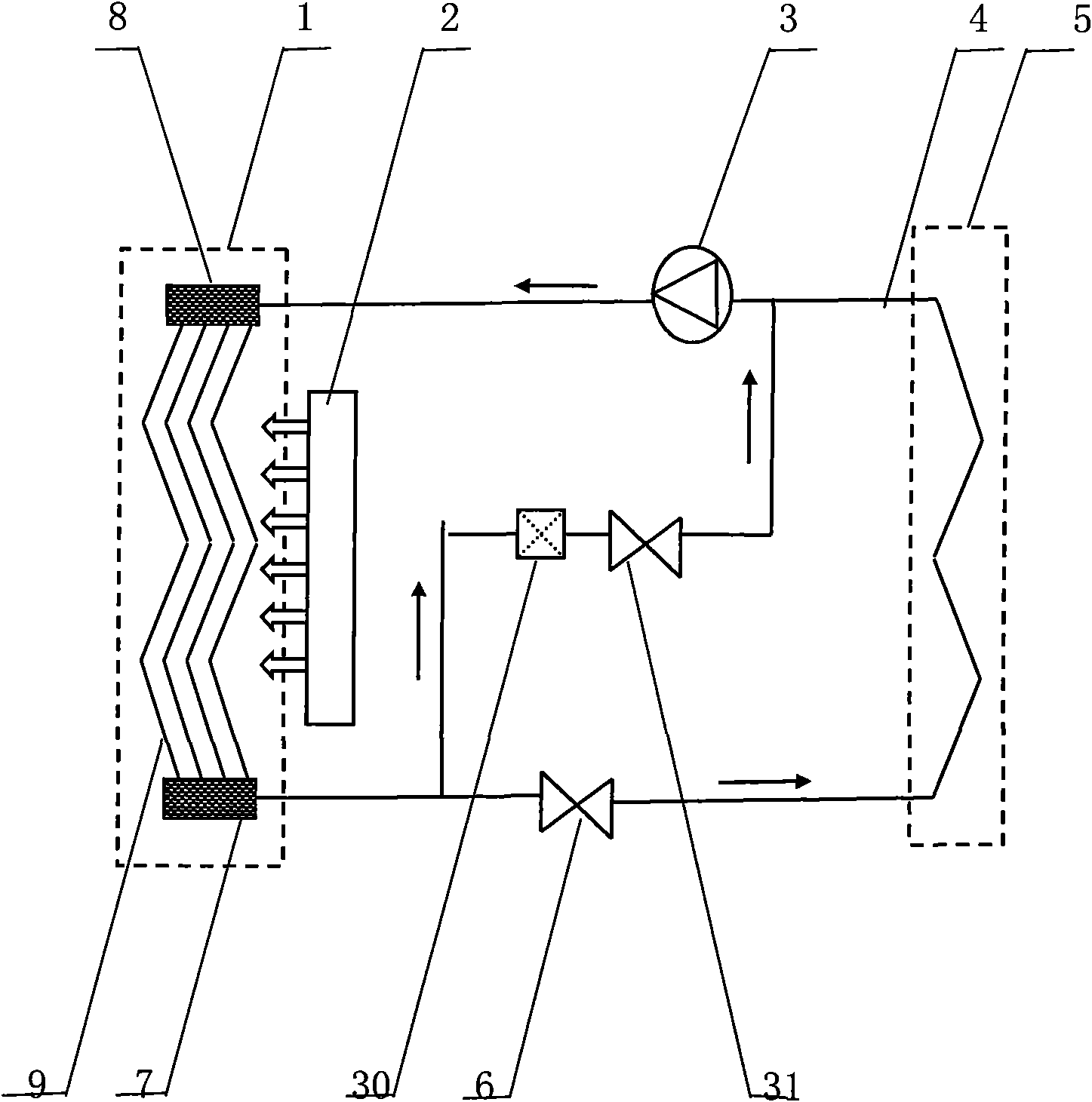
[0033] see figure 1 , reflecting a specific structure of the present invention, including an air source heat pump and a fan 2 mainly composed of an evaporator 5, a compressor 3, a condenser 1, and a main throttling device 6 connected with a working fluid circulation pipeline 4 in sequence. The hot air blower is also provided with a pressure relief diverter valve 30 and a secondary throttling device 31, the input end of the pressure relief diverter valve 30 is connected to the working fluid circulation pipeline 4 between the compressor 3 and the condenser 1, and the pressure relief diverter valve The output end of 30 is connected to the input end of the auxiliary throttling device 31 , and the output end of the auxiliary throttling device 31 is connected to the working medium circulation pipeline 4 between the evaporator 4 and the compressor 3 , and the connection point is close to the compressor 3 . Condenser 1 includes the air inlet and outlet on the shell and the shell and t...


PUM


Abstract

The present invention discloses a high temperature air source heat pump air heater used for drying, which comprises an air source heat pump and an air fan. The air source heat pump is mainly composed by connecting an evaporator, a compressor, a condenser, a main throttling device in sequence with the working substance circulating pipe. The value range of the ratio between the heat exchanging area of the air source heat pump and the input power of the compressor is 5.4-16m/kw. The value range of the ratio between the heat exchanging area of the condenser and the input power of the compressor is 4-12m/kw. The hot-air fan is also installed with a decompression dividing valve and an auxiliary throttling device. The condenser adopts the multi-path working substance pipe for forming a three-dimensional heat exchanging area which is provided with a plurality of layers of heat exchanging surfaces in the up-and-down direction and is provided with a plurality of heat exchanging intervals in the front-and-back direction. The technical solution of the invention has the advantages of greatly increased wind outlet temperature, stable operation of system, higher energy efficiency ratio and positive meaning for saving energy and reducing emission.

Description

technical field [0001] The invention relates to an air source heat pump fan for drying, in particular to a high temperature air source heat pump fan. Background technique [0002] The air source heat pump is mainly composed of compressor, evaporator, throttling device, condenser, working fluid circulation pipeline and other parts. Based on the principle of the reverse Carnot cycle, it is driven by electric energy, and effectively absorbs the unusable low-grade heat energy in the air through the heat transfer medium, and upgrades it to the available high-grade heat energy for use. Its working process: ①The heat transfer working medium enters the evaporator, and the working medium absorbs heat and evaporates in the evaporator. At this time, the working medium absorbs heat from the low-temperature heat source and then enters the compressor; ②After the working medium is compressed and heated by the compressor, The working fluid that becomes high temperature and high pressure is...

Claims


Application Information

Patent Timeline
IPC IPC(8): F26B21/00F25B39/02F25B41/04F25B41/06
Inventor 汤世国
Owner 湖南省浏阳市择明热工器材有限公司
Why Eureka
Try Eureka