
Method for detection by ultrasonic guided wave signals

An ultrasonic guided wave and signal technology, which is applied to the analysis of solids using sonic/ultrasonic/infrasonic waves, can solve problems such as inapplicability to long-distance detection, and achieve the effect of accurate detection results.

Active Publication Date: 2011-10-19
CHINA SPECIAL EQUIP INSPECTION & RES INST +1
View PDF0 Cites 0 Cited by
  • Summary
  • Abstract
  • Description
  • Claims
  • Application Information

AI Technical Summary

Problems solved by technology

The above method is mainly based on the sound field principle and is suitable for short-distance detection evaluation methods. The existing methods are not suitable for long-distance detection.

Method used


Image

  • Method for detection by ultrasonic guided wave signals
  • Method for detection by ultrasonic guided wave signals
  • Method for detection by ultrasonic guided wave signals

Examples


Embodiment Construction

[0028] The specific implementation manners of the present invention will be further described in detail below in conjunction with the accompanying drawings and embodiments. The following examples are used to illustrate the present invention, but are not intended to limit the scope of the present invention.

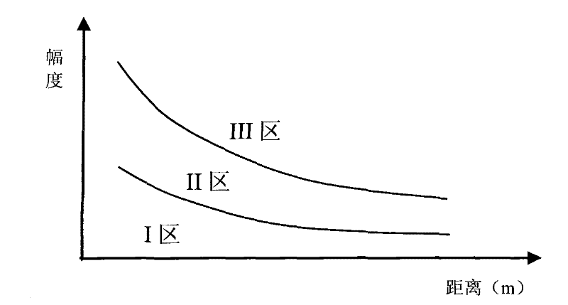
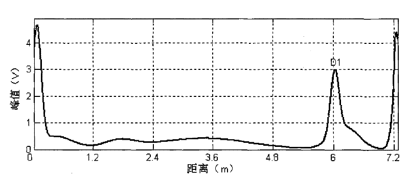
[0029] figure 1 A curve close to the coordinate system is the evaluation line, and a curve far away from the coordinate system is the waste judgment line. Make a standard sample pipe with an outer diameter of 57mm, a length of 46.45m, and a thickness of 3.5mm, and cut a groove with a sectional area loss of 12% at a distance of 1m from the left end. The sample pipe after cutting the groove is as follows: figure 2 as shown, figure 2 Among them, the first distance at the left end refers to the distance from the left end of the cut groove, the second distance refers to the distance from the first weld to the cut groove, and the distances after that refer to the distance be...


PUM

PropertyMeasurementUnit
thicknessaaaaaaaaaa

Abstract

The invention discloses a method for detection by ultrasonic guided wave signals, comprising the following steps of: obtaining a relationship graph on distance and amplitude of ultrasonic guided wave detection signal; dividing the graph into three regions by an abandonment line and an evaluation line; and carrying out signal evaluation and classification according to the relationship of the detected signal and the three regions. The abandonment line is obtained by the following steps of: preparing a standard sample pipeline; preparing a section surface loss defect A with the size of T at one end of the pipeline; arranging an ultrasonic guided wave sensor on the pipeline; subsequently moving the ultrasonic guided wave sensor on the pipeline; measuring the signal once when moving by a distance, thus obtaining the peak value of the defect A signal; obtaining a series of points by taking the distance from each measurement point to the defect A as an abscissa and taking the echo peak valuein the signal as an ordinate; and obtaining the abandonment line of the signal by carrying out curve fitting of the points. By considering the effects of welding seams and section surface loss on thedetection signals, the method determines the evaluation line and the abandonment line and leads the detection result to be exacter.

Description

technical field [0001] The invention relates to the technical field of nondestructive testing, in particular to a method for testing by means of ultrasonic guided wave signals. Background technique [0002] As a detection method emerging in recent years, ultrasonic guided wave has the advantage of a single-point excitation to achieve a distance detection, and it has been more and more widely used in occasions where other conventional methods such as pipelines and anchors cannot be detected. Due to the dispersion and multi-mode characteristics of guided waves, the evaluation of guided wave detection signals is an extremely difficult problem. At present, the existing ultrasonic guided wave evaluation methods are mostly related to the existing conventional detection methods, such as the national machinery industry standard non-destructive testing of pressure equipment JB4730-2005 on ultrasonic testing and In the quality grade evaluation part, the distance-amplitude curve shoul...

Claims


Application Information

Patent Timeline
Patent Type & Authority Patents(China)
IPC IPC(8): G01N29/11
Inventor 沈功田武新军刘德宇景为科陈卫东徐江
Owner CHINA SPECIAL EQUIP INSPECTION & RES INST
Learn More