Power system transmission line parameter synchronic measurement and recording device

A transmission line and synchronous measurement technology, applied in the direction of measurement devices, measurement value records, electrical devices, etc., can solve problems such as hidden dangers of staff and electrical equipment, impact optimization distribution, lack of information exchange and sharing, etc., to achieve engineering The effect of convenient and flexible application, improved accuracy, flexible and reliable networking and data remote transmission

Active Publication Date: 2011-01-26
SHENZHEN SHUANGHE ELECTRIC CO LTD
View PDF0 Cites 0 Cited by
  • Summary
  • Abstract
  • Description
  • Claims
  • Application Information

AI Technical Summary

Problems solved by technology

[0002] In 2007, China officially adopted IEC 61850 as the power industry standard, and started to change the status quo of repeated data collection of secondary equipment, lack of data integration and processing, and lack of information exchange and sharing
The manual workload is large, which affects the normal load power supply and the optimal distribution of the power flow. There are also disadvantages such as heavy measuring equipment, cumbersome operations, and time-consuming and labor-intensive operations.
Especially in the disconnection, grounding, closing and many operations of the line before and after the measurement, there are hidden dangers to the safety of the staff and electrical equipment. Moreover, the two ends of the line and the dispatching are generally connected by radio during the measurement, and the reliability is relatively high. Poor, easy to cause mistakes in coordination
At present, there is no unified modeling of fault recording and transmission line parameter synchronous measurement with the same hardware platform according to the IEC 61850 standard, so as to realize the synchronous measurement and recording of transmission line parameters of the interconnected grid

Method used


Image

  • Power system transmission line parameter synchronic measurement and recording device
  • Power system transmission line parameter synchronic measurement and recording device
  • Power system transmission line parameter synchronic measurement and recording device

Examples


Embodiment Construction

[0049] The present invention will be further described below with reference to the accompanying drawings and in conjunction with specific embodiments.

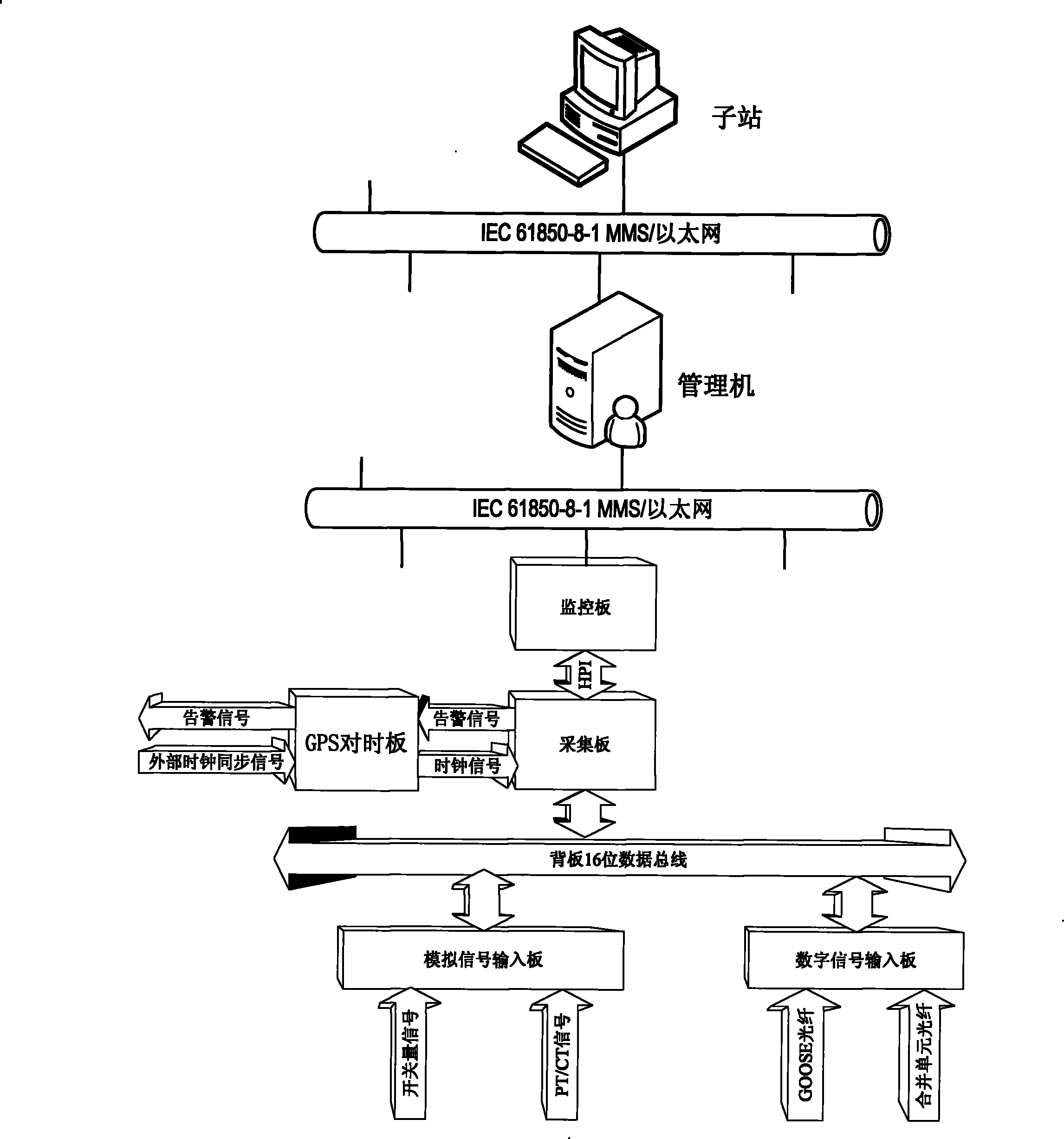
[0050] figure 1 It is a system structure diagram of a specific embodiment of the present invention, in which two signal input methods are given: merging unit + GOOSE network, or traditional PT / CT transmission signal + switch hard node.

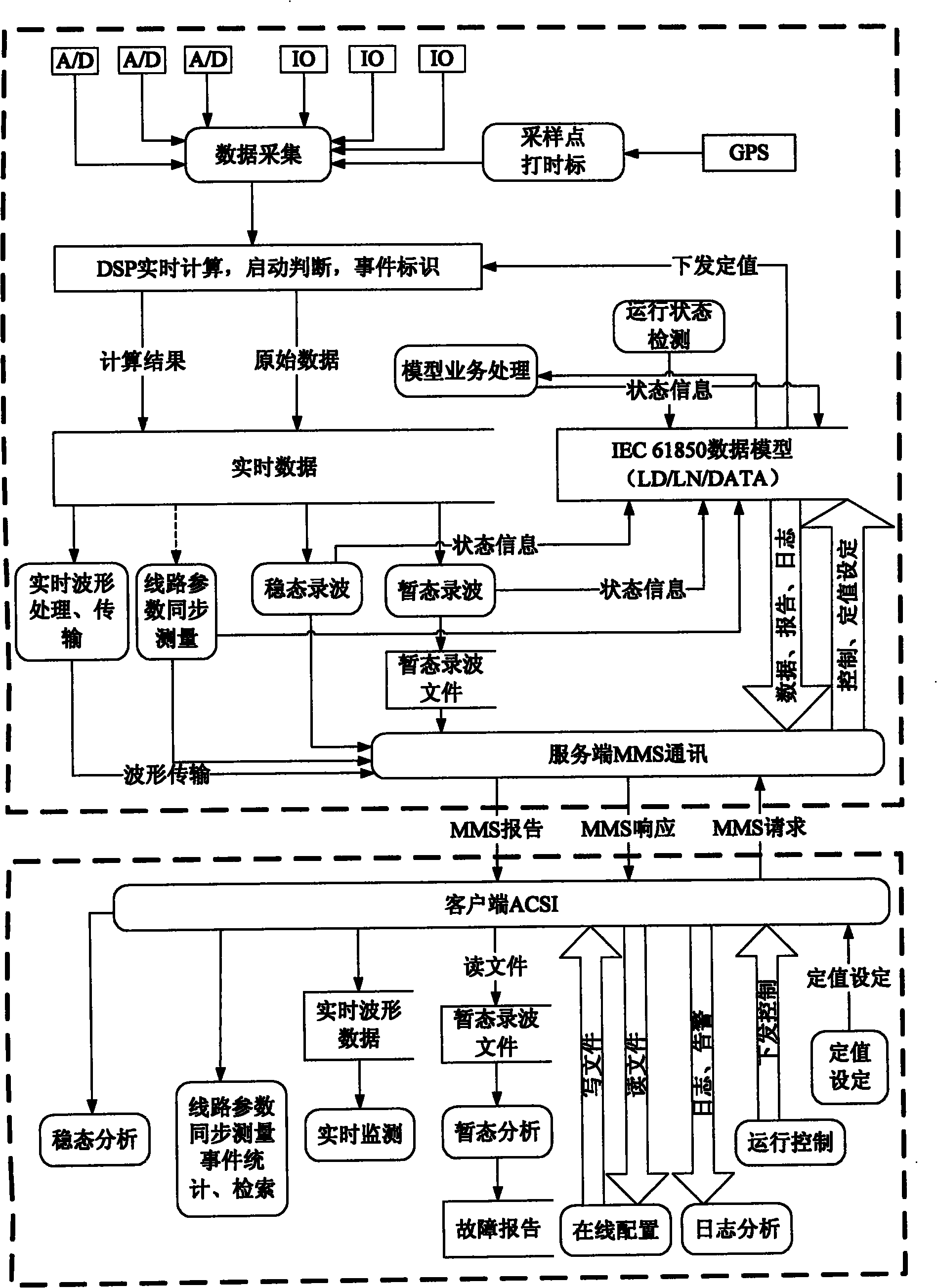
[0051] In this specific embodiment, the IEC 61850 model is uniformly established on the server side in accordance with the requirements of the IEC 61850 standard, and a fault recording logic module and a transmission line parameter synchronous measurement logic module with the same hardware platform are provided. The fault recording logic module performs start-up judgment according to the calculation results If there is a startup, a fault file will be generated to record transient faults and dynamic data, and to complete the offline analysis of the recorded wave data; the logic module for sync...


PUM


Abstract

The invention provides a power system transmission line parameter synchronic measurement and recording device. An IEC61850 model is uniformly established on a server end according to IEC61850 standardand a fault wave-recording logic model and a transmission line parameter measurement logic module with the same hardware platform are set on the server end and the system configuration is realized according to IEC61850-6 and an independent used configuration tool is formed. The fault wave-recording and transmission line parameter measurements respectively model different logic devices according to IEC61850 standard, namely the data record is realized when the power system is in failure and the synchro measurement of the power system transmission line parameters is realized, thereby solving the problem that the data, parameter read by manpower out-of-step for many times are not accurate in power failure. The accuracy of the line parameter is increased. The power system transmission line parameter synchronic measurement and recording device can be widely used for various application fields such as line wave recording, main-change wave recording, set wave recording, and transmission lineparameter synchro measurement.

Description

technical field [0001] The invention relates to monitoring and recording, in particular to a device for synchronous measurement and recording of transmission line parameters in a power system. Background technique [0002] In 2007, China formally adopted IEC 61850 as the power industry standard, and began to change the current situation of repeated data collection of secondary equipment, lack of data integration and processing, and lack of information exchange and sharing. The existing wave recorder can provide timely and accurate guarantee for user decision-making in the data integration and information exchange between IED devices, but it only sends data analysis to the master station in the event of a fault, and cannot perform synchronous measurement of power system transmission line parameters . The existing line parameter measurement method is blackout measurement, that is, the measured line must be powered off and disconnected from the grid, and the positive sequence ...

Claims


Application Information

Patent Timeline
Patent Type & Authority Patents(China)
IPC IPC(8): G01R19/00G01R21/00G01R23/00G01D9/00G01R27/00
Inventor 陈贤平熊敏俊路晓冰黎波任家友
Owner SHENZHEN SHUANGHE ELECTRIC CO LTD
Why Eureka
Try Eureka