Novel winding method for high-frequency transformer coils

A high-frequency transformer and coil technology, which is applied in the directions of transformer/inductor coil/winding/connection, inductance/transformer/magnet manufacturing, coil manufacturing, etc., can solve large energy loss, poor conversion energy efficiency, and high-frequency transformer loss and other issues to achieve the effects of improving conversion efficiency, saving production costs, and reducing energy loss

Inactive Publication Date: 2009-10-28
陈钦裕
View PDF0 Cites 9 Cited by
  • Summary
  • Abstract
  • Description
  • Claims
  • Application Information

AI Technical Summary

Problems solved by technology

[0003] 1. The loss of the high-frequency transformer is large, and it is necessary to upgrade the transformer to achieve the power output required by the adapter;
[0004] 2. Poor conversion efficiency affects the peripheral parts. The specification needs to be improved, the heat sink must also be enlarged, and the adapter shell must also be enlarged, resulting in an increase in the production cost of the adapter;
[0005] 3. Now talking about environmental protection and energy saving, due to poor conversion efficiency, the loss of energy is large, which wastes public electricity and increases social public expenditure, which does not meet the requirements of today's energy-saving environment.
[0006] Among them, the magnetic induction winding method of the initial high-frequency transformer primary and secondary coils is as follows: figure 1 As shown, it first winds the primary coil N1 on the high-frequency transformer coil skeleton, and then winds the secondary coil N2. This kind of conversion energy efficiency is the worst, because N1 needs to be wound first. Generally, N1 is used in the design of high-frequency transformers. The coil is very multi-layered. The outermost layer of N1 and N2 have the best induction, but the deeper the inner layer, the worse the induction, resulting in poor efficiency of converting energy and a large energy loss.

Method used


Image

  • Novel winding method for high-frequency transformer coils
  • Novel winding method for high-frequency transformer coils
  • Novel winding method for high-frequency transformer coils

Examples


Embodiment Construction

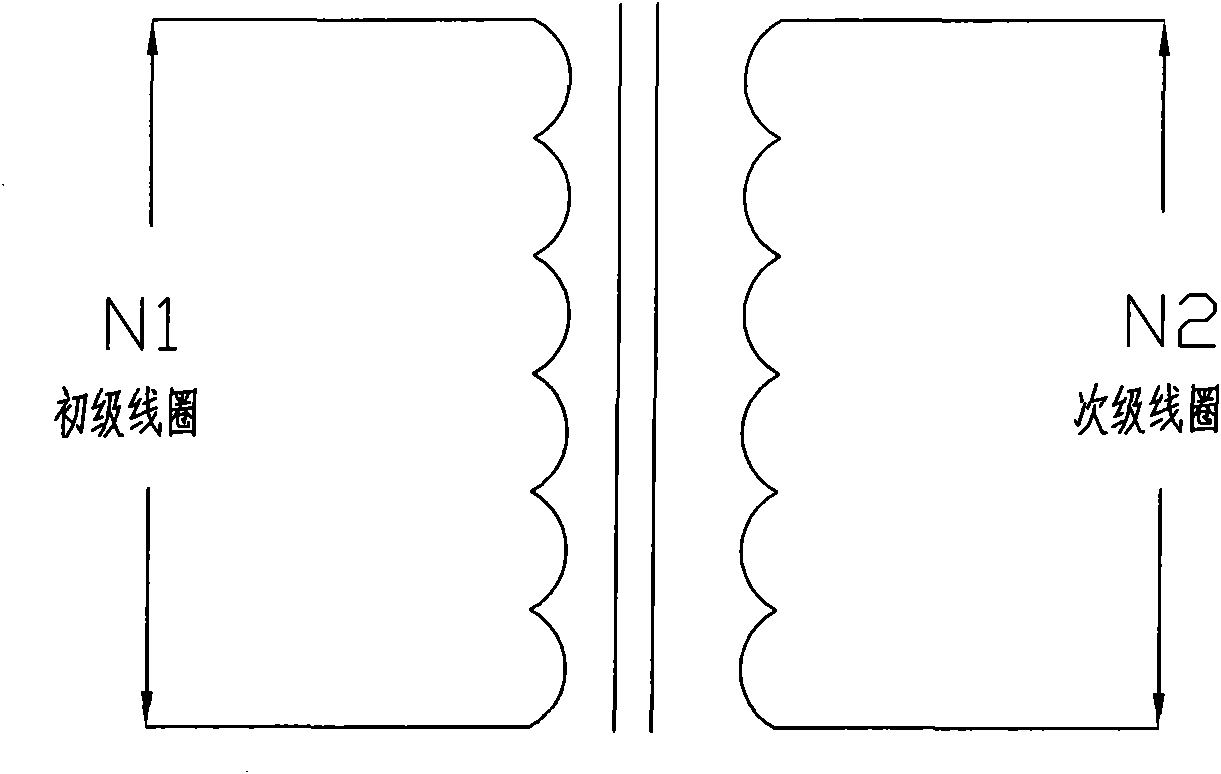
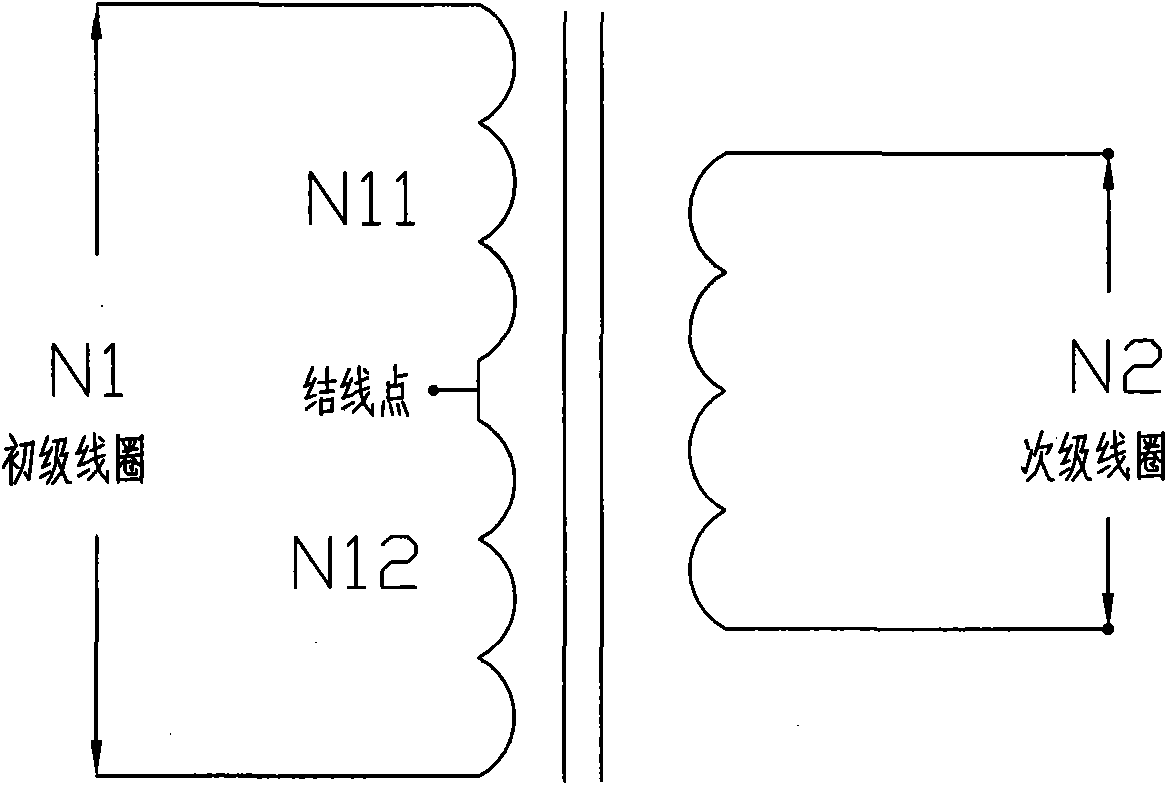
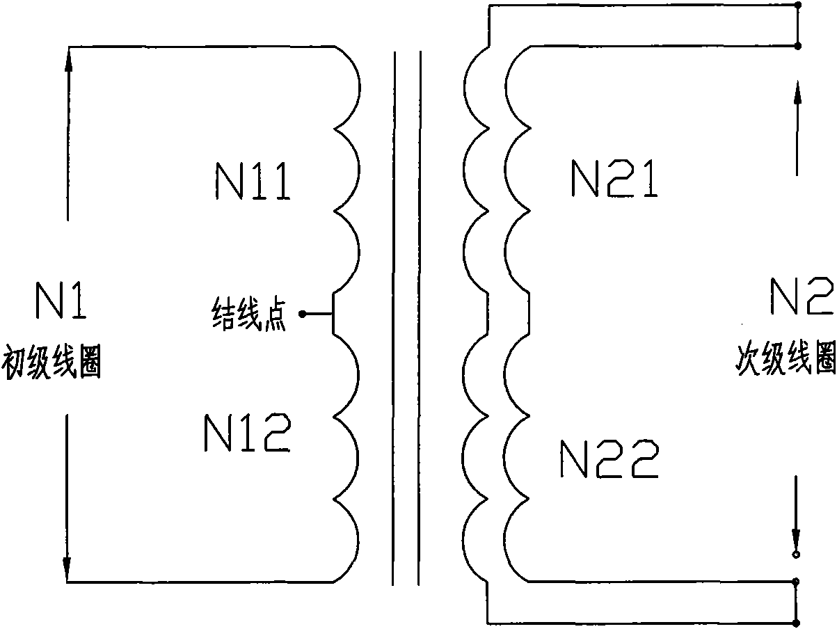
[0022] The present invention is a new winding method of a high-frequency transformer coil. First, the number of turns (number of turns) of the primary and secondary coils N1 and N2 is divided into several equal parts; One equal number of coil turns of the primary coil is then wound around one equal number of turns of the secondary coil, so that each equalized primary and secondary coil is wound crosswise until all the equalized primary and secondary coils are wound. Coil; the secondary coil is divided and wound with two or more strands of coil, and the number of parallel wound strands of the secondary coil is calculated according to the current to be passed. Through the cross-winding of the primary and secondary coils, the inductance between the coils can be improved, and the conversion efficiency is greatly improved compared with the transformer produced by the current winding method.

[0023] The number of turns of the primary and secondary coils N1 and N2 can be divided int...


PUM


Abstract

The invention relates to a novel winding method for high-frequency transformer coils, which comprises: firstly, dividing the winding number of a primary coil and a secondary coil into a plurality of equal parts; and secondly, winding a first equal part of the primary coil and winding the winding number of first equal parts of the secondary coil after the winding number of the first equal parts of the primary coil is wound, so that each equal part of the primary coil and each equal part of the secondary coil are wound in staggered form until all the equal parts of the primary coil and the secondary coil are wound, wherein the secondary coil adopts shunted and parallel winding of two or more strands of coil; and the parallel winding strand number of the secondary coil is calculated according to the current for the secondary coil to pass through. The transformer coils wound by the novel winding method can greatly improve the conversion efficiency; when the transformer coils are applied to switching power adapters, the energy and the electricity can be greatly saved and the environment-friendly requirement can be completely met; simultaneously the energy efficiency loss of transformers wound by the novel winding method is low, the transformers cannot generate high heat, and the safety requirement of electrical appliance components in the adapters does not need to be too high, thereby the loss and the volume can be reduced and the production cost can be saved.

Description

【Technical field】 [0001] The invention relates to a new winding method of a high-frequency transformer coil of a switching power supply adapter. 【Background technique】 [0002] The high-frequency transformer is a very important part in the switching power adapter. The AC input of the adapter can be stepped down by the secondary coil and then rectified to output to achieve the DC voltage we want. device, so the primary coil voltage can be coupled to the secondary coil by magnetic induction. Since it is the energy conversion method between magnetoelectricity, there will be a certain amount of energy loss. If the primary and secondary coil magnetic induction cannot achieve the best condition, That will lose a lot of energy in the transformer, so that the high-frequency transformer itself is prone to overheating due to its own loss, and it is easy to cause the energy loss of the switching power adapter to increase or even burn out. The impact and economic value are as follows: ...

Claims


Application Information

Patent Timeline
Patent Type & Authority Applications(China)
IPC IPC(8): H01F27/28H01F41/06H01F41/071
Inventor 陈钦裕
Owner 陈钦裕
Why Eureka
Try Eureka