Eureka AIR delivers breakthrough ideas for toughest innovation challenges, trusted by R&D personnel around the world.

Battery pack protective circuit applying micro-electromechanical system (MEMS) switch

A technology of micro-electromechanical systems and protection circuits, which is applied in the direction of emergency protection circuit devices and electrical components, and can solve the problems of inability to realize control circuit integration and high power consumption

Inactive Publication Date: 2009-10-28
TIANJIN VAST TECH
View PDF0 Cites 6 Cited by
  • Summary
  • Abstract
  • Description
  • Claims
  • Application Information

AI Technical Summary

Problems solved by technology

For electric bicycles or electric vehicles, the power consumption of the switch on-resistance will be greater
The MOSFET switch is generally made with a special process and cannot be integrated with other control circuits

Method used


Image

  • Battery pack protective circuit applying micro-electromechanical system (MEMS) switch
  • Battery pack protective circuit applying micro-electromechanical system (MEMS) switch
  • Battery pack protective circuit applying micro-electromechanical system (MEMS) switch

Examples


Embodiment Construction

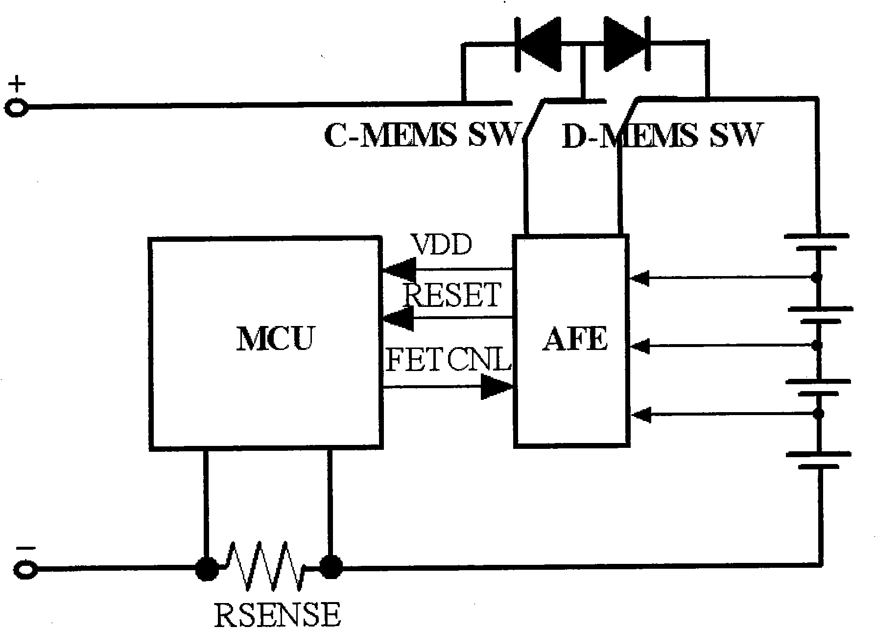
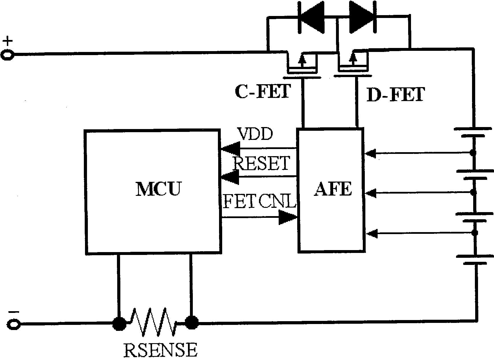
[0030] Such as figure 1 The present invention as shown provides a kind of overall scheme of battery, battery pack charging and discharging protection circuit, it is characterized in that application microelectromechanical system MEMS (micro electromechanical system) switch replaces MOSFET charging and discharging switch, the battery of the present invention design, battery pack charging and discharging The functional block diagram of the discharge protection circuit is as follows: figure 1 shown.

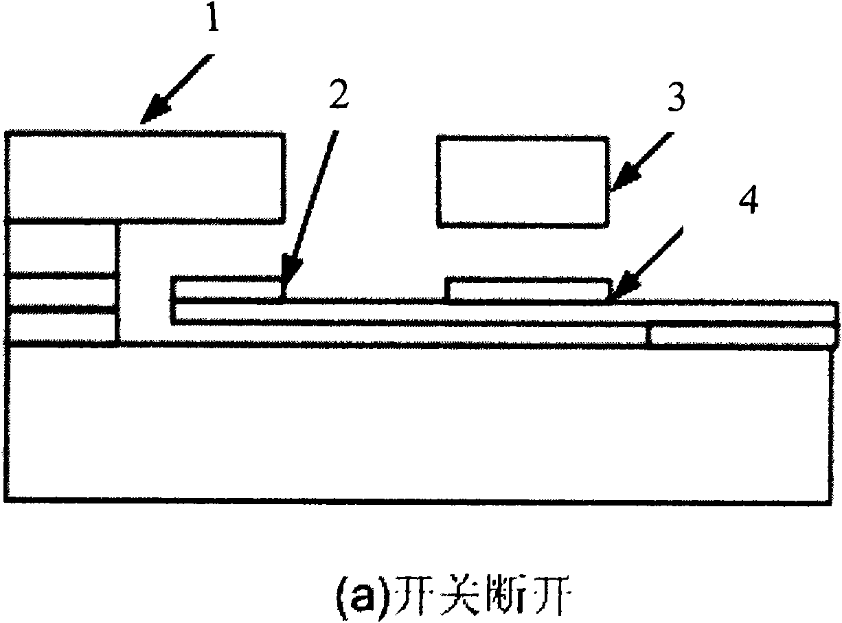
[0031] Two electrostatic MEMS switches connected in series are connected at the negative terminal of the battery pack, and the negative terminal of the battery pack is connected to the transmission line of the first electrostatic MEMS switch, the first of the first electrostatic MEMS switch The electrodes are connected to the transmission line of the second electrostatic MEMS switch, and the first electrode of the second electrostatic MEMS switch is used as the output terminal of...


PUM


Abstract

The invention relates to a battery pack protective circuit applying a micro-electromechanical system (MEMS) switch, which can be ued for a rechargeable battery or a battery pack, for example a lithium battery pack used for a notebook computer and a rechargeable protective circuit of an electric bicycle or an electric car. The charge and discharge protective circuit comprises a battery, an analog front end (AFE) circuit of a charge and discharge control circuit of a battery pack, a micro-control unit (MCU) and one or more micro-electromechanical system (MEMS) switches. The invention can reduce static power consumption of the batter or the battery pack in a process of charging and discharging, provides higher degree of isolation in a disconnection process and improves the density of integration of a charge and discharge circuit.

Description

technical field [0001] The invention belongs to a battery protection circuit, in particular to a battery group protection circuit using a micro-electromechanical system (MEMS) switch. Background technique [0002] At present, devices requiring high-power rechargeable batteries (groups) such as notebook computers, electric bicycles and electric vehicles have been widely used, and the life of these rechargeable batteries directly determines the continuous working time of the equipment, so how to effectively carry out high-power batteries Charging, discharging, and automatically managing, displaying and protecting the charging and discharging process have become hot topics. The existing battery (group) charge and discharge protection control circuit can realize effective control and protection of the high-power battery charge and discharge process. The traditional battery (group) charge and discharge protection circuit with MOS field effect transistor (MOSFET) switch function b...

Claims


Application Information

Patent Timeline
Patent Type & Authority Applications(China)
IPC IPC(8): H02H7/18
Inventor 马建国李景虎喻明艳
Owner TIANJIN VAST TECH
Why Eureka
Eureka Blog
Learn More