
Power clamping static protection circuit

An electrostatic protection and power supply technology, applied in the field of power supply clamp electrostatic protection circuit, can solve the problem of not being able to help the input and output unit electrostatic current discharge well, and achieve the effect of saving area and improving electrostatic protection capability.

Active Publication Date: 2009-10-28
SHANGHAI HUAHONG GRACE SEMICON MFG CORP
View PDF4 Cites 11 Cited by
  • Summary
  • Abstract
  • Description
  • Claims
  • Application Information

AI Technical Summary

Problems solved by technology

[0003] However, this common, centralized clamping circuit is only placed in the power supply unit
If the number of input and output units is too large and the distance between some units and the power supply unit is too large, the clamping circuit cannot help the input and output units to discharge static electricity well.

Method used


Image

  • Power clamping static protection circuit
  • Power clamping static protection circuit

Examples


Embodiment Construction

[0011] The present invention will be described in further detail below in conjunction with the accompanying drawings.

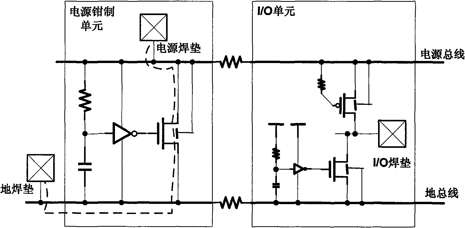
[0012] figure 1 is a schematic diagram of a previous power supply clamping unit circuit. The circuit in the power supply clamping unit is an independent power supply electrostatic protection clamping circuit. figure 1 The curve formed by the dotted line segment in the figure shows the path of the electrostatic current discharge when the electrostatic discharge test (ESD zapping) occurs between the VDD Pad and the GND Pad. It will pass through the electrostatic protection circuit in the input / output unit (I / O unit).

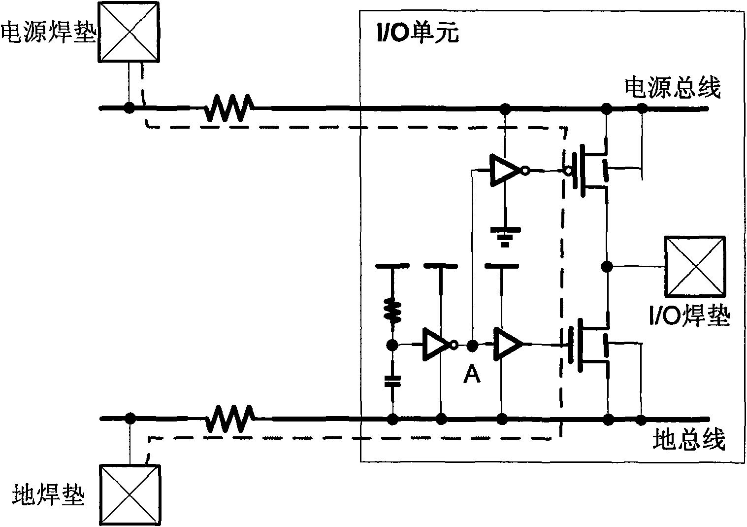
[0013] figure 2 It is a schematic diagram of the source clamping electrostatic protection circuit of the present invention. In the I / O unit, the original ESDNMOS trigger circuit is modified. The output (point A) of the original starting circuit is output to the gate of the NMOS through the forward buffer, and output to the gate of the PMOS ...


PUM


Abstract

The invention relates to a power clamping static protection circuit, which comprises a power weld pad, a ground weld pad and an input / output unit; the power weld pad is connected with a power bus, andthe ground weld pad is connected with a ground bus; the input / output unit comprises a first resistor, a capacitor, a first inverter, a PMOS triode, a NMOS triode, and an input / output weld pad; the power clamping static protection circuit also comprises a positive buffer and a second inverter used for controlling the PMOS triode and the NMOS triode to discharge static. The power clamping static protection circuit realizes partial static discharge route from the power to the ground by using the existing static protection apparatus inputted and outputted to the ground and the static protection apparatus inputted and outputted to the power of the input and output unit in the premise of not increasing the areas of the input and output unit, thereby releasing the areas of a power / ground unit for arranging a decoupling capacitor to achieve the effect of saving area.

Description

technical field [0001] The invention relates to the field of semiconductor integrated circuits, in particular to a power clamp electrostatic protection circuit. Background technique [0002] In the design of electrostatic protection circuit for semiconductor integrated circuits, the design of power supply clamping circuit is very important. Due to the limited area of ​​the input and output unit, the size of the electrostatic protection device will not be too large. Compared with the input and output units, the power supply unit has more space for electrostatic protection. Generally, the size of the power supply clamping device is designed to be relatively large, and the design of the trigger circuit is also more complicated to provide a more sensitive electrostatic trigger to help the input and output circuits. Perform electrostatic current discharge. [0003] However, this common, centralized clamping circuit is only placed in the power supply unit. If the number of inpu...

Claims


Application Information

Patent Timeline
IPC IPC(8): H02H9/00
Inventor 何军单毅
Owner SHANGHAI HUAHONG GRACE SEMICON MFG CORP
Learn More