Traction mechanism drive with a compensating device for vibration reduction

A technology of traction transmission and balance device, which is applied in the direction of valve device, balance rotating body, vibration suppression adjustment, etc., and can solve the problem of high dynamic load of the transmission device

Inactive Publication Date: 2009-10-28
IWIS MOTORSYSTEME GMBH & CO KG
View PDF2 Cites 7 Cited by
  • Summary
  • Abstract
  • Description
  • Claims
  • Application Information

AI Technical Summary

Problems solved by technology

As a result, the dynamic load on the transmission is still relatively high over a large operating range and for other vibration orders

Method used


Image

  • Traction mechanism drive with a compensating device for vibration reduction
  • Traction mechanism drive with a compensating device for vibration reduction
  • Traction mechanism drive with a compensating device for vibration reduction

Examples


Embodiment Construction

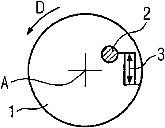
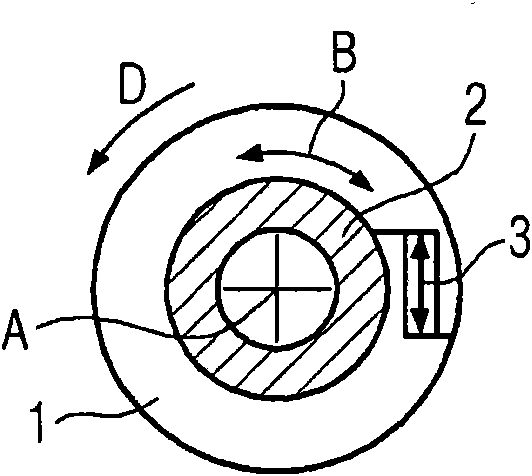
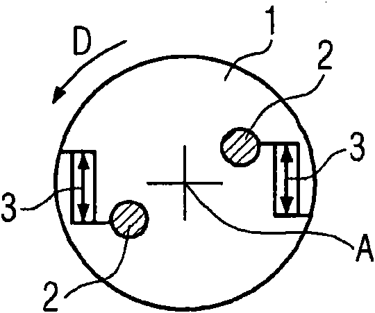
[0037] Figure 1a to Figure 1c Different embodiments of a compensating device for reducing vibrations in a traction drive are shown in plan view from the front. One or two balancing masses 2 are respectively movably arranged on the mass support body 1 of the balancing device and the balancing masses 2 are respectively equipped with an adjustment mechanism 3 , which adjusts the balancing masses 2 in the direction of rotation D of the shaft 4 On or against the direction of rotation D of the shaft 4.

[0038] exist Figure 1aIn the balancing device shown, only one balancing mass 2 is arranged on the mass support body 1 at a distance from the axis of rotation A of the driven shaft 4 . The balancing mass 2 is moved by means of the adjustment mechanism 3 , which is supported on the mass support body 1 , preferably on a circular arc of the center of gravity of the balancing mass 2 about the axis of rotation A along or against the direction of rotation of the shaft. In addition to t...


PUM


Abstract

The present invention relates to a traction mechanism drive with a compensating device for vibration reduction of a driven shaft (4), for example a camshaft, a water pump shaft or an injection pump shaft of an internal combustion engine, having a drive wheel (9) which is coupled to the shaft, having a drive mechanism, and having at least one compensating mass (2) which is relatively movable in the traction mechanism drive and having at least one actuating mechanism (3) for moving the compensating mass. Here, the compensating mass is movable in or counter to the rotational direction of the shaft, and the actuating mechanism is embodied as a tangentially acting actuator for moving the compensating mass. The invention also relates to a method for vibration reduction in a traction mechanism drive, having a driven shaft, having a drive wheel and having a drive mechanism, wherein at least one actuating mechanism moves at least one compensating mass which is relatively movable in the traction mechanism drive, having the steps: activating the actuating mechanism, moving the compensating mass and generating a compensating torque at the driven shaft. In the case of a control drive with a camshaft adjusting system for the angular adjustment of the control time, the camshaft which is movable relative to the traction mechanism drive can simultaneously be used as a compensating mass for vibration reduction.

Description

technical field [0001] The invention relates to a traction drive (Zugmitteltrieb), in particular for an internal combustion engine, with a balancing device for reducing vibrations in the traction drive, the traction drive having a driven shaft, a Transmission wheels, transmission means, at least one balancing mass relatively movable in or against the direction of rotation of a shaft in a traction drive, and at least one adjustment mechanism for moving the at least one balancing mass (Stellmechanismus ). Furthermore, the invention relates to the use of a camshaft adjustment system (Nockenwellen-Verstellsystems) for reducing vibrations in a traction drive and a corresponding method for reducing vibrations in a traction drive. Background technique [0002] In the development of modern motor vehicles, so-called NVH behavior (noise, vibration, harshness) is becoming increasingly important. In addition to the buyer's desire to have a high level of vibration comfort, a lower nois...

Claims


Application Information

Patent Timeline
Patent Type & Authority Applications(China)
IPC IPC(8): F16F15/14F16F15/36
CPCF16F15/36F16F15/1414F01L1/024F16F15/145F16F15/1457
Inventor S·拉茨S·贝尔默
Owner IWIS MOTORSYSTEME GMBH & CO KG
Why Eureka
Try Eureka