Method of designing minute flow rate controller with entrance throttle groove

A technology of flow control device and design method, applied in the direction of valve device, mechanical equipment, sliding valve, etc.

Inactive Publication Date: 2009-10-28
FUJIKIN INC +1
View PDF2 Cites 1 Cited by
  • Summary
  • Abstract
  • Description
  • Claims
  • Application Information

AI Technical Summary

Problems solved by technology

Since the flow rate of the needle valve increases rapidly after opening the valve, it is difficult to supply the flow rate to the above-mentioned fine space. For example, the maxi

Method used


Image

  • Method of designing minute flow rate controller with entrance throttle groove
  • Method of designing minute flow rate controller with entrance throttle groove
  • Method of designing minute flow rate controller with entrance throttle groove

Examples


Embodiment Construction

Preferred Mode for Carrying Out the Invention

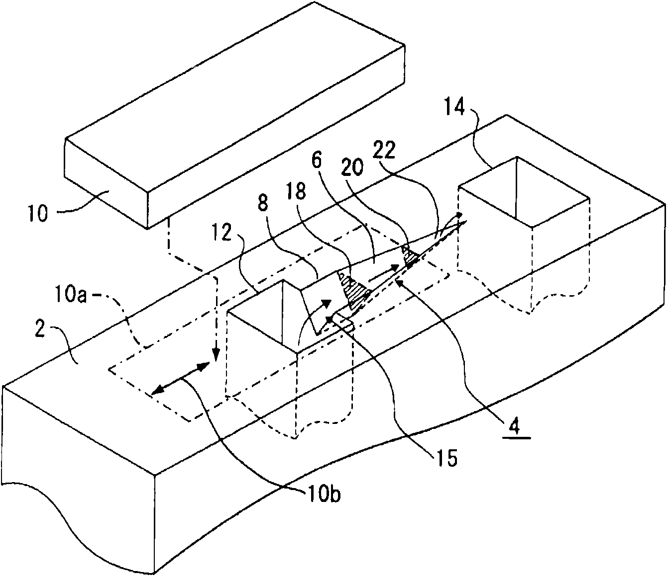
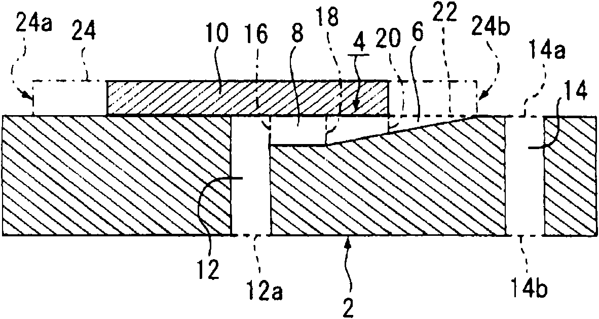
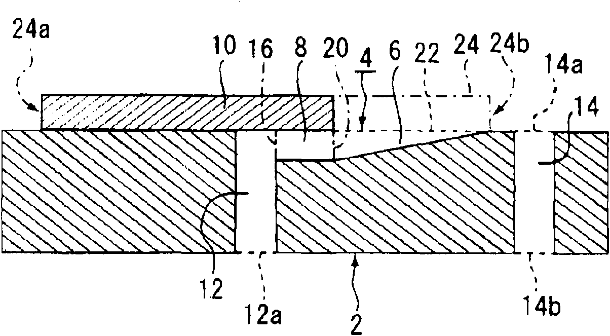
[0039] figure 1 It is a schematic explanatory diagram of the minute flow control device of the present invention. The basic structure of the micro-flow control device consists of a valve core 2 formed with a throttling groove 4 and a flow adjustment slider 10 sliding on the valve core 2 . The above-mentioned throttling groove 4 is composed of a main throttling groove 6 and an inlet throttling groove 8, and the above-mentioned flow adjustment slider 10 is in sliding contact with the upper surface of the valve core, and the above-mentioned main throttling groove 4 and the inlet throttling groove 8 function as a flow path. Features. When the above-mentioned flow rate adjustment slider 10 is located at the upper sliding contact position 10a of the valve core 2, the fluid flowing in from the inflow passage 12 flows into the inlet throttle groove 8 from the inflow portion 15, passes through the above-mentioned main throttle groove 6,...


PUM


Abstract

A method of designing a minute flow rate controller that is capable of accurately controlling the minute flow rate of a fluid and realizing desired valve characteristics without inducing any unsteadiness of fluid flow and has a simple configuration with respect to a throttle groove for controlling the fluid flow rate. With respect to a minute flow rate controller comprising inflow passage (12) for introducing a fluid, valve member (2) furnished with main throttle groove (6) for causing the introduced fluid to flow from a starting end toward a finishing end thereof, fluid outflow port (20) opened with an optional cross section by a flow rate regulating member and outflow passage (14) for leading out the fluid flowing out from the fluid outflow port (20), there is provided a method of designing the minute flow rate controller with entrance throttle groove, comprising providing entrance throttle groove (8) communicably preceding the starting end position of the main throttle groove (6), and, on the basis of a relational expression derived from the momentum equation of the fluid flowing through the entrance throttle groove (8) and the main throttle groove (6), determining the size of the entrance throttle groove (8) so as to exhibit a desired flow resistance.

Description

technical field [0001] The present invention relates to a flow control device for controlling the flow rate of liquid and gas, more specifically, it relates to controlling the microscopic flow of fluid (liquid, gas) in micro-sized flow paths, fluid action environments, reactors, etc. Design method of micro-flow control device for flow. Background technique [0002] In recent years, the miniaturization and integration of chemical reaction systems have attracted attention as new technical issues in synthetic chemistry, analytical chemistry, semiconductor industry and bioengineering industry. It plays an important role in the high precision and efficiency of chemical reaction control such as chemical vapor deposition system and synthetic chemical experiment system. In such technological trends, chemical reactions in tiny spaces with reaction volumes ranging from nanoliters to microliters are being promoted, so-called microreactors, to improve reaction yields, shorten reaction ...

Claims


Application Information

Patent Timeline
IPC IPC(8): F16K3/00
CPCF16K3/0218F16K3/32
Inventor 世古口言彦
Owner FUJIKIN INC
Why Eureka
Try Eureka