Automatic indexing fixture

An automatic indexing and fixture technology, applied in the direction of clamping, manufacturing tools, supports, etc., can solve problems such as inability to achieve accurate indexing, achieve the effects of improving precision, improving production efficiency, and realizing automation

Inactive Publication Date: 2009-11-04
WUHU HONGJIN MACHINE TOOL
View PDF0 Cites 9 Cited by
  • Summary
  • Abstract
  • Description
  • Claims
  • Application Information

AI Technical Summary

Problems solved by technology

[0003] The existing above-mentioned fixtures are generally used in rotary processing, and adopt a combin...

Method used


Image

  • Automatic indexing fixture
  • Automatic indexing fixture

Examples


Embodiment 1

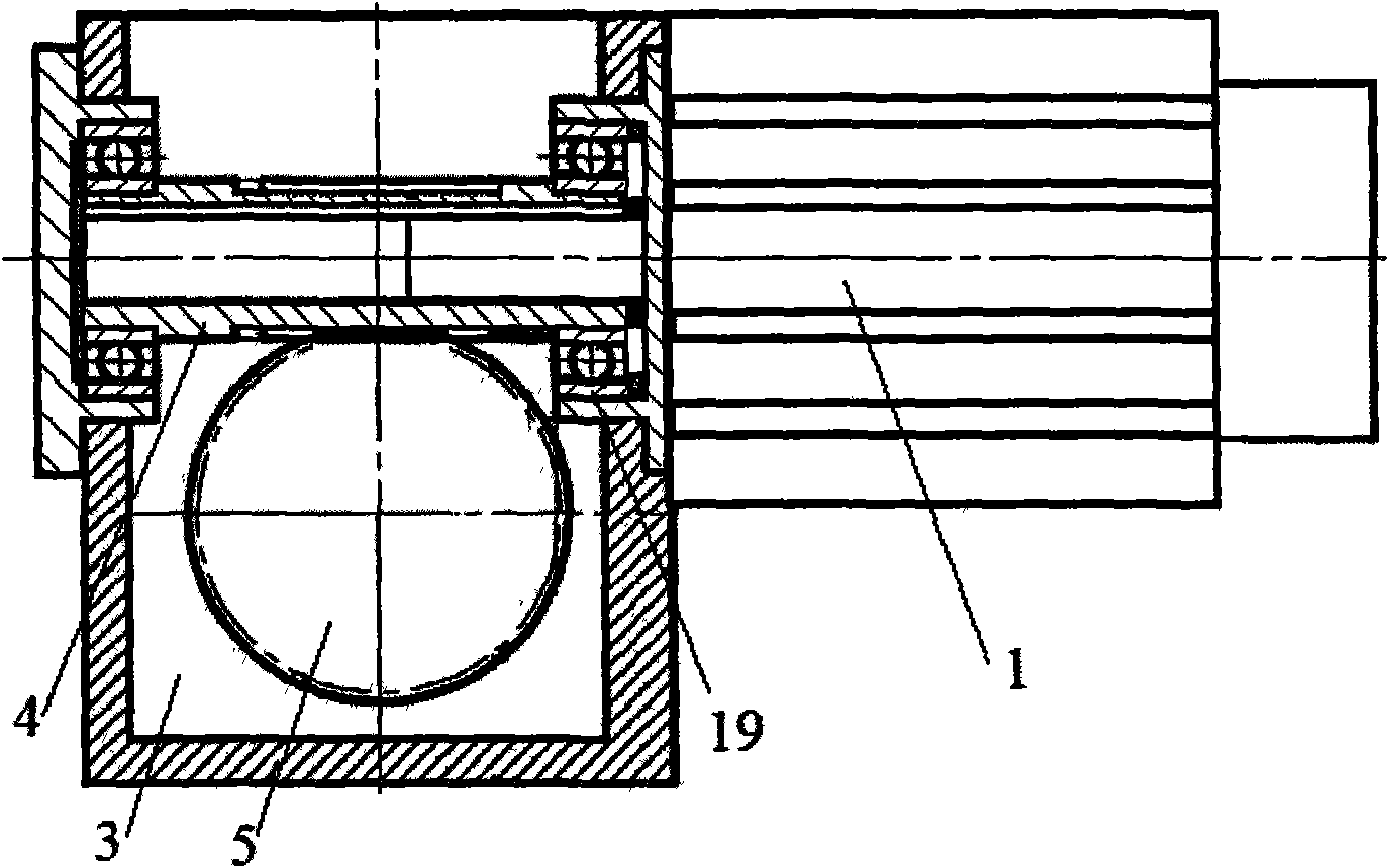
[0031] Such as figure 2 As shown, the driving structure of the worm gear mechanism of the present invention adopts the servo motor 1, and the hole of the worm shaft 4 in the worm gear mechanism is matched with the shaft of the servo motor 1 and is tightly connected.

[0032] Servo motor is a motor that controls the operation of mechanical components in a servo system. It is an auxiliary motor indirect speed change device. Its function is to convert the voltage signal into torque and speed to drive the control object, which can make the control speed and position accuracy very accurate. The encoder is set in the electrical control system of the machine tool, and the accuracy of the servo motor depends on the accuracy (number of lines) of the encoder.

[0033] Using the servo motor as the driving device of the indexing mechanism in the machine tool fixture can improve the indexing accuracy of the indexing device, and can realize the automatic control of the indexing, so that i...

Embodiment 2

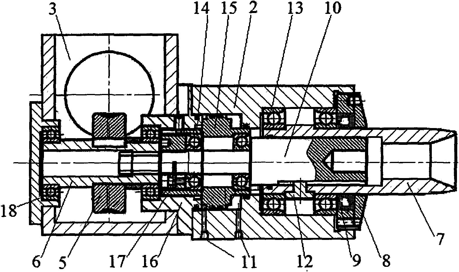
[0035] Such as figure 1 As shown, the pneumatic transmission mechanism of the present invention is provided with a cylinder 2, and the jacket 7 is installed in the hole of the cylinder 2 through a jacket bearing 13. There are two jacket bearings 13, which are distributed at a certain distance along the axial direction of the jacket 7, and play a supporting role on the jacket 7.

[0036] The above-mentioned structure enables relative rotation between the jacket 7 and the cylinder 2 , that is, the jacket 7 can rotate and index in the state of clamping the workpiece, or rotate.

[0037] Cylinder 2 is a fixed part, and its function is to form the execution part driven by air pressure together with cylinder piston 15 described below.

Embodiment 3

[0039] Such as figure 1 As shown, the end of the cylinder 2 according to the present invention is provided with an inner skeleton oil seal 9 tightly sleeved on the outer circle of the jacket 7, and a sealing gland 8 is provided, and the inner skeleton oil seal 9 is fixed by the sealing gland 8 , the sealing gland 8 is fastened on the end of the cylinder 2 .

[0040] The inner frame oil seal 9 and the sealing gland 8 are adopted, and the inner frame oil seal 9 is pressed tightly on the end of the cylinder 2 by the sealing gland 8, so as to play a good sealing effect on the jacket bearing 13.


PUM


Abstract

The invention discloses an automatic indexing fixture which is provided with a pneumatic transmission mechanism, an air cylinder piston (15) is sheathed on a clamping pull rod (10) by a bearing, and the air cylinder piston (15) is fastened and connected with the clamping pull rod (10) along the axial direction; a dividing mechanism of the automatic indexing fixture is a worm and gear mechanism, a hole of a worm-wheel shaft (6) of the worm and gear mechanism is connected with the other section of the clamping pull rod (10) by spline structure in a way of sliding fit. By adopting the technical proposal, clamping and indexing can be carried out simultaneously, a machine tool is not needed to be stopped, the indexing can be completed by the coordinated actions of the pneumatic transmission mechanism and the worm and gear mechanism when the clamping is carried out, and the automation of clamping and indexing can be realized, so that the production efficiency is improved; an actuating motor can be used for realizing electric-drive indexing, and the accuracy of indexing can be improved.

Description

technical field [0001] The invention belongs to the technical field of mechanical manufacturing process equipment, and relates to a machine tool fixture structure, more specifically, the invention relates to an automatic indexing fixture. Background technique [0002] In the existing machine tool fixtures, for optical shaft parts with small diameters, spring collets are generally used for clamping. The workpiece is clamped to produce a small amount of deformation; the outer tapered surface of the spring collet matches the inner tapered surface of the jacket, the jacket is fixed on the spindle or the fixed structure of the machine tool, and the inner end of the spring chuck is connected with the pull rod. Pulling makes the collet move axially relative to the jacket, and due to the action of the outer cone surface of the collet and the inner cone surface of the jacket, the collet shrinks and clamps the workpiece. [0003] The existing above-mentioned fixtures are generally us...

Claims


Application Information

Patent Timeline
IPC IPC(8): B23Q3/00
Inventor 冯晓飞瞿国权
Owner WUHU HONGJIN MACHINE TOOL
Why Eureka
Try Eureka