Oil conservator moisture absorber with convenient silica gel replacement

A technology that is easy to replace and oil conservator, applied in the direction of transformer/inductor cooling, etc., can solve the problems of excessively long dimensions, misjudgment of operation monitoring, heavy weight, etc., to save time and maintenance costs, and ensure normal breathing. , the effect of weight reduction

Inactive Publication Date: 2009-11-04
CHINA XD ELECTRIC CO LTD
View PDF0 Cites 12 Cited by
  • Summary
  • Abstract
  • Description
  • Claims
  • Application Information

AI Technical Summary

Problems solved by technology

[0003] Since the size of the moisture absorber is determined according to the volume of the oil conservator (that is, the breathing capacity), the required moisture absorber will be very large on high-voltage and large-capacity power transmission and transformation equipment, such as figure 1 The dehumidifier with a single-tank structure has a length of 1 meter and a weight of nearly 35 kg, which is difficult to carry and replace
The silica gel in the tank of the dehumidifier becomes discolored due to moisture, and the dehumidifier loses its function of filtering moisture in the air. At this time, it is necessary to replace the silica gel in the tank. However, due to the long size and heavy weight of the dehumidifier itself, manual The operation is difficult, and some lifting equipment is required, which will delay a certain amount of time
At the same time, during the replacement process, if the valve connected to the oil conservator above the dehumidifier is closed, it is equivalent to cutting off the passage between the capsule in the oil conservator and the atmosphere. It is a hidden danger for the transformer
If the valve is opened for replacement, a small amount of moist air and dust will enter the capsule of the oil conservator through the joint pipe, which will increase the weight of the bottom of the capsule, easily cause false oil level phenomenon on the oil gauge, and cause misjudgment of operation monitoring

Method used


Image

  • Oil conservator moisture absorber with convenient silica gel replacement
  • Oil conservator moisture absorber with convenient silica gel replacement
  • Oil conservator moisture absorber with convenient silica gel replacement

Examples


Embodiment 1

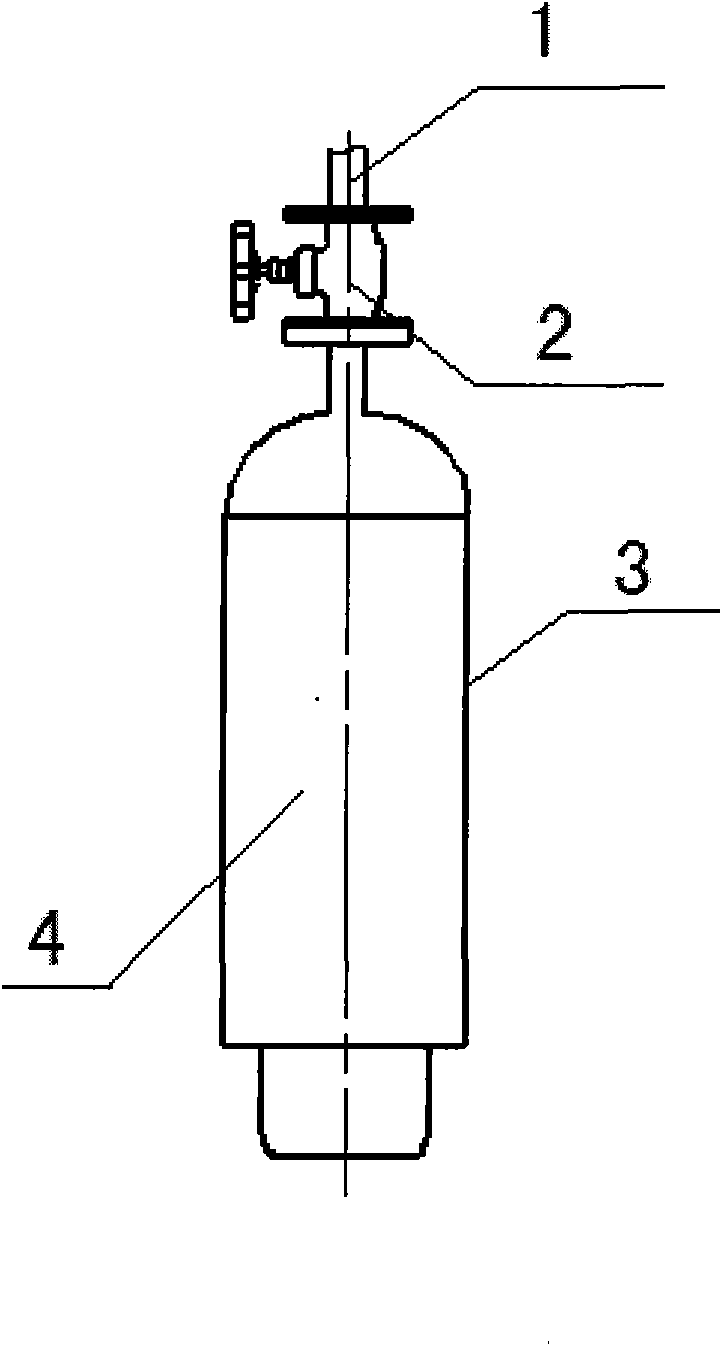
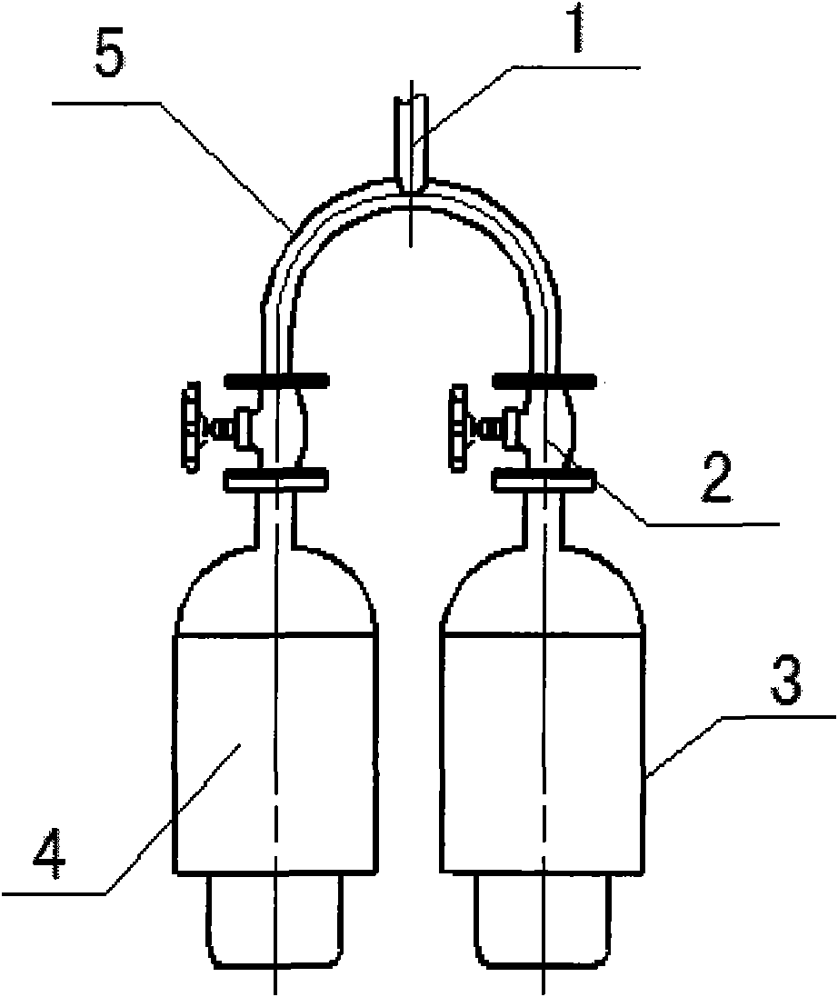
[0017] Such as figure 2 As shown, the new structure is changed from the original oil conservator connecting pipe 1 connected with the moisture absorber to only one tank body 3, to connecting two side-by-side tank bodies through an inverted U-shaped tee pipe 5, the inverted U-shaped The bending radius of the three-way pipe 5 is relatively large, and there is no dead angle. When replacing the silica gel 4 in one of the tanks, it can ensure the unimpeded flow of the oil conservator capsule and the breathing channel of the other tank. Thereby, the original single-can bulky large moisture absorber is optimized into a two-can lightweight moisture absorber. Its length is 3 / 4 of the original length; the weight is 1 / 2 less.

Embodiment 2

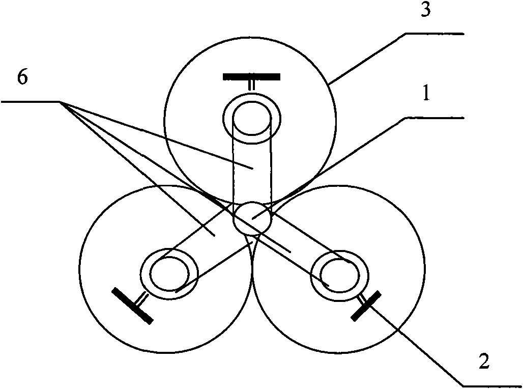
[0019] Such as image 3 As shown, the tank bodies 3 are three arranged in a character shape, and a Y-shaped four-way pipe 6 communicating with the connecting pipe 1 is connected to the vacuum valves 2 of the three tank bodies. When one of the tanks is replaced with the silica gel 4, it can ensure the unimpeded flow of the oil conservator capsule and the breathing passages of the other two tanks.


PUM


Abstract

The invention relates to an oil conservator moisture absorber with convenient silica gel replacement, which comprises tank bodies communicated with an oil conservator capsule, wherein the tank bodies are filled with silica gel. The oil conservator moisture absorber is characterized in that the number of the tank bodies is at least two, the tank opening of each tank body is provided with a vacuum valve, and the vacuum valves are connected with connecting pipes communicated with the oil conservator capsule through multi-pass pipes. On the premise of ensuring the respiratory capacity of the moisture absorber, the prior moisture absorber with one tank is changed into a moisture absorber with at least two tanks, each single moisture absorber has smaller volume and lighter weight, and the oil conservator moisture absorber can be carried manually to replace the silica gel by one person, is convenient and quick, and saves certain time and maintenance cost, and simultaneously, when the silica gel is affected with damp, the oil conservator is ensured to be in a normal respiratory state during the whole replacement.

Description

technical field [0001] The invention relates to a moisture absorber, in particular to a moisture absorber used for oil storage cabinets of power transmission and transformation equipment such as oil-immersed transformers and reactors. Background technique [0002] The dehumidifier used in the early transformer oil conservator was a single-tank structure. The inner cavity of the capsule of the oil conservator communicated with the atmosphere through the dehumidifier. Oil tank capsules. [0003] Since the size of the moisture absorber is determined according to the volume of the oil conservator (that is, the breathing capacity), the required moisture absorber will be very large on high-voltage and large-capacity power transmission and transformation equipment, such as figure 1 The dehumidifier with a single tank structure has a length of 1 meter and a weight of nearly 35 kg, which is difficult to carry and replace. The silica gel in the tank of the dehumidifier becomes disco...

Claims


Application Information

Patent Timeline
Patent Type & Authority Applications(China)
IPC IPC(8): H01F27/14
Inventor 李希蔡继雯朱建华赵炜
Owner CHINA XD ELECTRIC CO LTD
Why Eureka
Try Eureka