Device, system and method for steel rail parameter automatic measurement

An automatic measurement and rail technology, applied in the field of optical measurement, can solve problems such as detachment and measurement failure, and achieve the effects of improving measurement accuracy, avoiding measurement failure, and avoiding manual errors

Inactive Publication Date: 2009-11-11
BEIJING JIAOTONG UNIV
View PDF3 Cites 10 Cited by
  • Summary
  • Abstract
  • Description
  • Claims
  • Application Information

AI Technical Summary

Problems solved by technology

The invention uses a laser to automatically measure the displacement of the rail, and transmits the measured value to the central processing unit through a wireless communication network, thereby realizing remote monitoring of the displacement and temperature stress of the observation point, but due to the need to install a rail displacement measurement unit on the rail, these The measuring unit has a certain weight and size, and it is easy to be separated by rail vibration, resulting in measurement failure

Method used


Image

  • Device, system and method for steel rail parameter automatic measurement
  • Device, system and method for steel rail parameter automatic measurement
  • Device, system and method for steel rail parameter automatic measurement

Examples


Embodiment 1

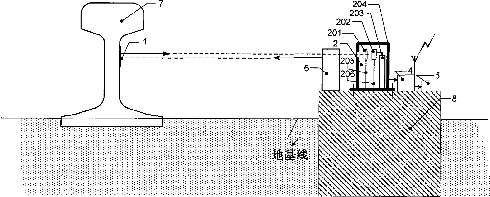
[0061] figure 1 It is a composition schematic diagram of the rail parameter automatic measuring device of the first embodiment of the present invention. Such as figure 1 As shown, the automatic rail parameter measurement device includes a rail longitudinal displacement automatic measurement unit, a data transmission unit 4 and a power supply module 5 .

[0062] The rail longitudinal displacement automatic measurement unit includes a marker 1 and a marker receiver and processor 2, and may also include a light source compensator 6.

[0063] Mark receiving and processor 2 is made up of imaging lens 201, photoelectric position detector 202, signal processor 203, installation box 204, first support 205 and second support 206, and it is arranged on the optical path that can detect mark 1, and Correspondingly installed on the fixed pile 8 on the side of the rail, and connected with the data transmission unit 4 . The imaging lens 201 is fixed in the installation box 204 through the...

Embodiment 2

[0079] Figure 6 It is a schematic diagram of the rail parameter automatic measurement system of the second embodiment of the present invention. Such as Figure 6 As shown, the rail parameter automatic measurement system includes two or more rail parameter automatic measurement devices and a common central processing unit 9, and every two rail parameter automatic measurement devices form a rail parameter automatic measurement device group, and each group of rail parameter The automatic measurement device group includes at least one rail temperature automatic measurement unit 3, and the rail temperature automatic measurement unit 3 is connected with the data transmission unit 4 of the rail parameter automatic measurement device and the power supply module 5, and the data transmission unit of all rail parameter automatic measurement devices is shared The same central processing unit 9, and all data transmission units are connected to the central processing unit 9 by wired or wi...

Embodiment 3

[0139] Figure 9 It is a schematic diagram of the principle of measuring rail temperature stress by the rail parameter automatic measurement system according to the third embodiment of the present invention. Figure 9 Among them, the rail temperature automatic measurement unit 3 is fixed on the fixed pile 8 at the side of the rail by bonding or mechanical connection. The connection relationship of other parts is the same as that of the second embodiment.

[0140] Figure 10 It is a schematic composition diagram of the rail parameter automatic measurement device with the rail temperature automatic measurement unit according to the third embodiment of the present invention. Such as Figure 10 As shown, during the measurement, the rail temperature automatic measurement unit 3 obtains the temperature value of the rail edge fixed pile 8, and since the distance between the rail 7 and the corresponding rail edge fixed pile 8 is not enough to produce a temperature difference, it is...


PUM


Abstract

The invention discloses a device, a system and a method for steel rail parameter automatic measurement, which belongs to the technical field of optical measurement. The steel rail parameter automatic measurement device comprises a steel rail longitudinal-displacement automatic measurement unit, a data transmission unit and a power supply module or further comprises a central processing unit and a steel rail temperature automatic measurement unit; the steel rail longitudinal-displacement automatic measurement unit comprises a marker, a marker receiving processor and a rail side spud pile or further comprises a light source compensator; the steel rail longitudinal-displacement automatic measurement can be realized through the steel rail longitudinal-displacement automatic measurement unit; the steel rail parameter automatic measurement system comprises two or more steel rail parameter automatic measurement devices and a common central processing unit; and the steel rail temperature stress automatic measurement can be realized through the steel rail parameter automatic measurement system. The invention can realize the all-weather measurement, has high measuring accuracy, can automatically search the section with the largest temperature stress for the steel rail and further avoids an accident.

Description

technical field [0001] The invention belongs to the technical field of optical measurement, and in particular relates to a rail parameter automatic measurement device, system and method thereof. Background technique [0002] Seamless track, also known as welded long steel track, can meet the actual needs of high-speed and heavy-duty railway transportation, and is a major trend in the development of railway technology. At present, seamless lines are widely used on China's railway transportation trunk lines. When dozens or even hundreds of standard rails are welded together to form a seamless line, due to the resistance of the fasteners and the resistance of the ballast bed, the long rails can only expand with heat and contract with cold within 100 meters at both ends. The middle part (called the fixed area) cannot be deformed, that is, the rail is not allowed to expand with heat and contract with cold, so the corresponding longitudinal temperature stress is stored in the rai...

Claims


Application Information

Patent Timeline
Patent Type & Authority Applications(China)
IPC IPC(8): B61K9/08G01B11/02
Inventor 冯其波杨婧
Owner BEIJING JIAOTONG UNIV
Why Eureka
Try Eureka