Routine inspection device and method for rigid cage guides

一种罐道、刚性的技术,应用在刚性罐道巡检装置领域,能够解决刚罐道安装位置不能保证等距、刚罐道变形等问题,达到避免人工作业误差、安全可靠吸附、提高检测速度的效果

Active Publication Date: 2017-02-15
CHINA UNIV OF MINING & TECH
View PDF5 Cites 8 Cited by
  • Summary
  • Abstract
  • Description
  • Claims
  • Application Information

AI Technical Summary

Problems solved by technology

When working with this well construction method, the installation position of the steel channel cannot be guaranteed to be equidistant from the fixed position. In this case, the steel channel is more likely to be deformed due to external factors. How to detect the defects of the steel channel in real time and accurately Detecting and solving in time is a major difficulty in the research direction of coal mine safety detection

Method used


Image

  • Routine inspection device and method for rigid cage guides
  • Routine inspection device and method for rigid cage guides
  • Routine inspection device and method for rigid cage guides

Examples


Embodiment Construction

[0050] The present invention will be further explained below in conjunction with the accompanying drawings.

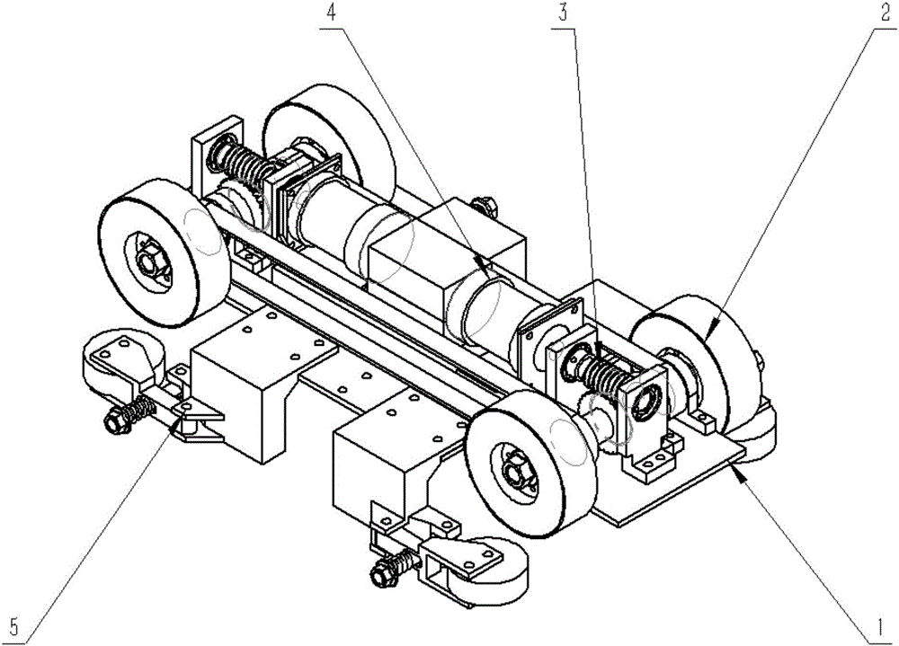
[0051] like figure 1 As shown, a rigid tank road inspection device of the present invention includes a main body bottom plate 1 and a moving part 2 , a transmission part 3 , a driving part 4 , a guide part 5 and a casing 6 arranged on the main body bottom plate 1 .

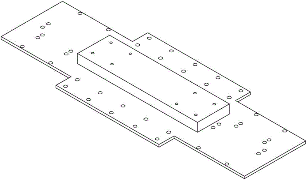
[0052] like figure 2 As shown, a number of assembly holes are opened on the main body bottom plate 1 for realizing bolt connection between various components.

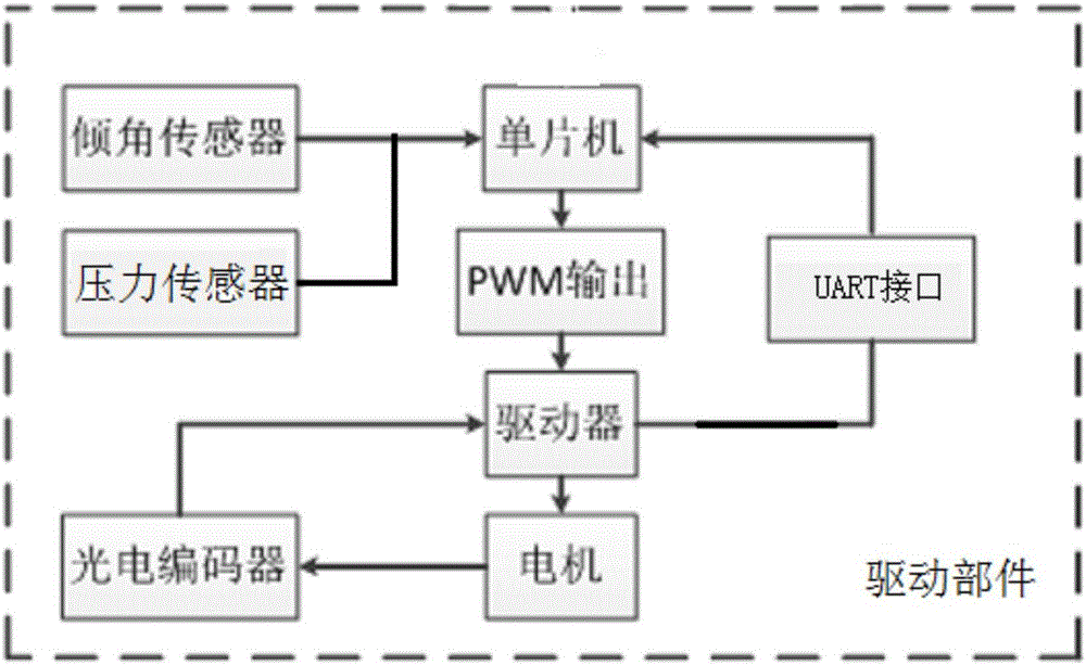
[0053] like image 3 and 4 As shown, the housing 6 is arranged in the middle of the main body bottom plate 1, and the driving part 4 is arranged inside the housing 6. The driving part 4 includes an inclination sensor and a pressure sensor, and the inclination sensor and the pressure sensor are connected to the single-chip microcomputer, and the single-chip microcomputer is connected to the driver 4-3, and the driver 4- 3 Connect the DC brushle...


PUM


Abstract

The invention discloses a routine inspection device and method for rigid cage guides. The routine inspection device comprises a moving component, a transmission component, a driving component, a guiding component and an outer shell, wherein the moving component, the transmission component, the driving component, the guiding component and the outer shell are arranged on a main body base plate. The driving component comprises an inclinometer and a pressure sensor, wherein the inclinometer and the pressure sensor are connected with a single chip microcomputer; the single chip microcomputer is connected with a driver; the driver is connected with brushless direct-current motors; and an output shaft of each brushless direct-current motor is provided with an optical-electricity encoder connected with the driver. The moving component comprises driving output shafts and driven output shafts; wheel flanges on the driving output shafts and wheel flanges on the driven output shafts are connected with wheel hubs; permanent magnets are arranged in the wheel hubs; and a rubber surface layer is arranged outside each wheel hub. The transmission component comprises worms, worm wheels, synchronous belt pulleys and synchronous belts, wherein each worm is connected with the output shaft of the corresponding brushless direct-current motor; each worm wheel is arranged on the corresponding driving output shaft and engaged with the corresponding worm; the synchronous belt pulleys are arranged on the driving output shafts and the driven output shafts; and the synchronous belts are wound on the synchronous belt pulleys. The guiding component comprises guiding wheels. By means of the routine inspection device and method for the rigid cage guides, rigid cage guide inspection speed is increased, and production efficiency of a coal mine enterprise is improved indirectly.

Description

technical field [0001] The invention belongs to the field of mine hoisting system equipment detection, and in particular relates to a rigid tank road inspection device and inspection method. Background technique [0002] At present, the detection of rigid tank roads in mines in my country mainly relies on maintenance personnel, and there is no independently driven independent inspection equipment, so the detection accuracy of rigid tank road defects is low. When the inclination deformation of the rigid tank reaches a certain level, the running stability of the lifting container will decrease, which will bring safety hazards to the lifting system. [0003] With the increase of coal mine mining depth, whether the circular shaft cross-sectional shape is the optimal solution has attracted the attention of many scholars at home and abroad. Some scholars have proposed that the shaft cross-sectional shape should be designed according to different mining depths and mining pressures....

Claims


Application Information

Patent Timeline
Patent Type & Authority Applications(China)
IPC IPC(8): B62D57/024G01D21/02
CPCB62D57/024G01D21/02B66B7/1246E21D7/02G01M5/0025B66B7/02B62D55/265E21F17/00G01M5/00
Inventor 周公博高肇兴唐超权朱真才曹国华周坪陈浩
Owner CHINA UNIV OF MINING & TECH
Why Eureka
Try Eureka