Supercharge Your Innovation With Domain-Expert AI Agents!

Horizontal type double-casing industrial coal powder boiler

A technology for pulverized coal boilers and boiler shells, which is applied to steam boilers, water heaters, lighting and heating equipment, etc., and can solve the problem of small and medium-sized industrial pulverized coal boilers whose structure cannot be directly applied, with different structures and transportation methods, and the scale of use Different requirements are required to achieve full and stable flame combustion, good adjustment and control, and prolong the effect of flue gas flow

Active Publication Date: 2009-11-11
CHINA COAL RES INST CCRI ENERGY SAVING TECH CO LTD
View PDF0 Cites 1 Cited by
  • Summary
  • Abstract
  • Description
  • Claims
  • Application Information

AI Technical Summary

Problems solved by technology

These boilers generally use raw coal in the form of lump coal and mixed coal as fuel, and cannot directly use fine-grained coal powder as fuel, so the fuel combustion efficiency is low
At the same time, due to the different requirements for the scale of use of large-scale power plant pulverized coal boilers used in power plants, their existing structural forms cannot be directly applied to small and medium-sized industrial pulverized coal boilers.
However, general oil and gas shell boilers use different fuels, and their structures and delivery methods are also different. Therefore, fuel oil and gas boilers cannot be directly used as fine-grained pulverized coal boilers.

Method used


Image

  • Horizontal type double-casing industrial coal powder boiler
  • Horizontal type double-casing industrial coal powder boiler

Examples


Embodiment Construction

[0011] The present invention will be described in detail below in conjunction with the accompanying drawings and embodiments.

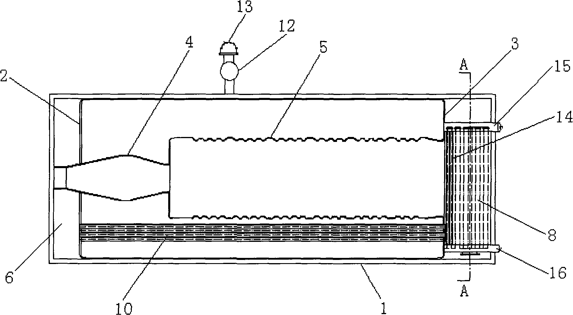
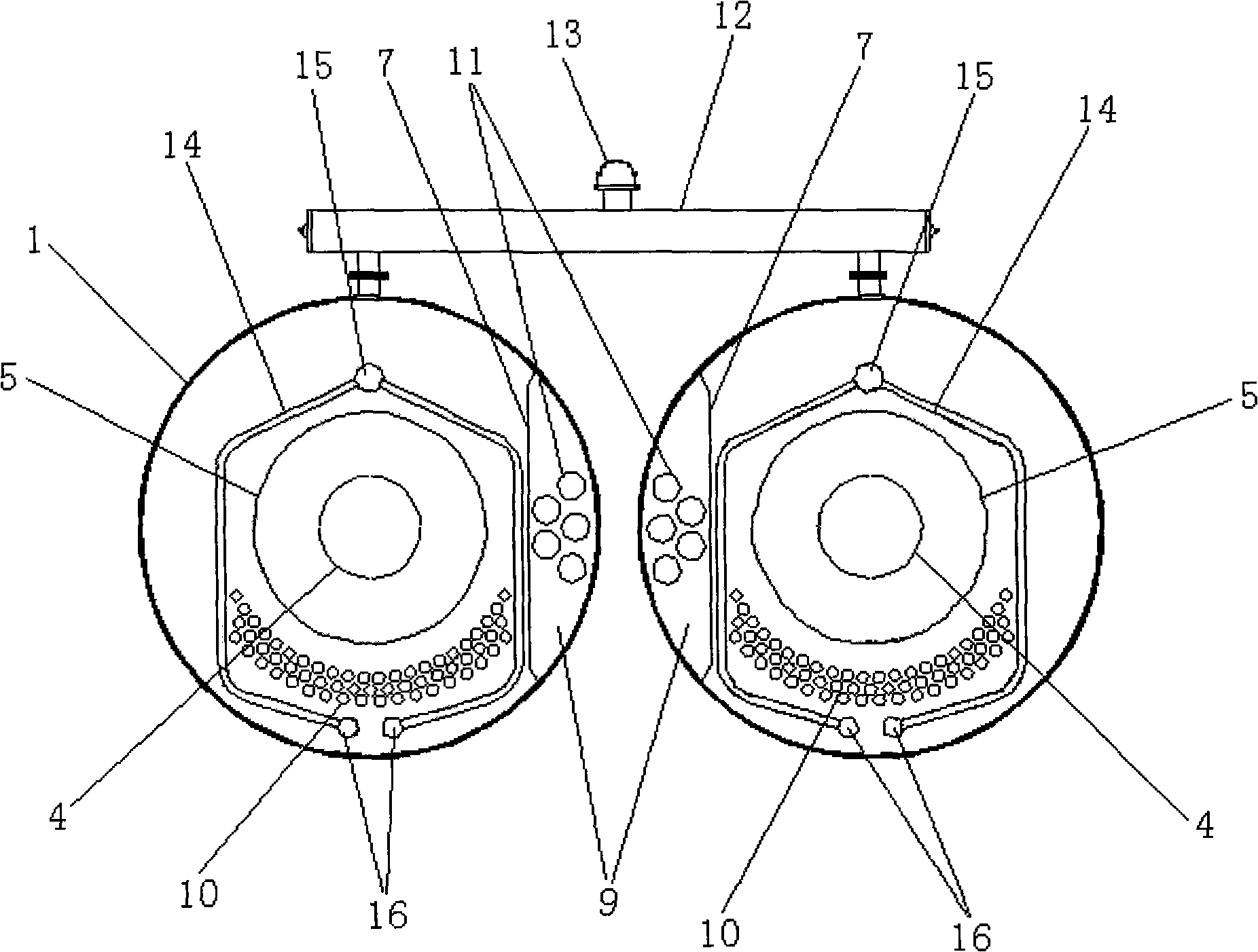
[0012] Such as figure 1 , figure 2 As shown, the present invention includes two cylindrical pot shells 1 placed side by side, and a front end plate 2 and a rear end plate 3 are respectively arranged at the front and rear of each pot shell 1 . A conical pre-chamber 4 is perforated in the middle of the front end plate 2 in the axial direction, and the pre-chamber 4 is composed of an expanding cone and a constricting cone. The inlet ends of the two pre-combustion chambers 4 are respectively connected to pulverized coal burners (not shown in the figure), and the outlet ports are respectively connected to one end of a horizontal furnace 5 placed horizontally in the pot shell 1, and the other end of the furnace 5 is connected to the The rear end plate 3 communicates. A front smoke box 6 is formed between the front end of the pot shell 1 and the front en...


PUM


Abstract

The invention relates to a horizontal type double-casing industrial coal powder boiler which is characterized by comprising two abreast and transversely arranged cylindrical boiler casings, wherein a front end plate and a back end plate are respectively arranged at the front part and the rear part in each boiler casing; a conical precombustion chamber respectively and axially penetrates the middle part of the front end plate, the outlet end of the precombustion chamber is respectively communicated with ends of horizontal type boiler flues transversely arranged in the boiler casing and other ends of the boiler flues are communicated with the back end plate; a front smokebox is formed between the front end of the boiler casing and the front end plate, the rear end of the boiler casing and the back end plate are divided into a left part and a right part through a partition board and a rear smokebox and a smoke collection chamber are respectively formed at the left part and the right part; a water wall circuit is vertically arranged in the rear smokebox; a group of two-pass smoke pipes communicated with the front smokebox and the rear smokebox is respectively and axially arranged at the lower parts in the middles of the two boiler flues, a group of three-pass smoke pipes communicated with the front smokebox and the smoke collection chamber is respectively and axially arranged in the boiler casing at the opposite side of the two boiler casings; and steam drums communicated with the two boiler casings are arranged at the tops of the two boiler casings and hot water or steam outlet openings are arranged on the steam drums. The invention can be widely used in any situation where the small and medium-sized industrial coal powder boilers are required.

Description

technical field [0001] The invention relates to an industrial pulverized coal boiler, in particular to a double boiler shell horizontal industrial pulverized coal boiler. Background technique [0002] At present, traditional industrial coal-fired boilers are generally divided into layer-fired furnaces, chamber-fired furnaces and fluidized fluidized furnaces, among which layer-fired furnaces (including reciprocating furnaces, chain furnaces, etc.) are the most widely used. These boilers generally use raw coal in the form of lump coal and mixed coal as fuel, and cannot directly use fine-grained coal powder as fuel, so the fuel combustion efficiency is low. At the same time, the existing structure of the large power plant pulverized coal boilers used in power plants cannot be directly applied to small and medium-sized industrial pulverized coal boilers due to the different requirements on the scale of use. However, general oil-fired and gas-fired shell boilers have different s...

Claims


Application Information

Patent Timeline
IPC IPC(8): F24H1/44F22B31/08
Inventor 王乃继纪任山冀飞周建明何海军范玮肖翠微张帆
Owner CHINA COAL RES INST CCRI ENERGY SAVING TECH CO LTD
Features
  • R&D
  • Intellectual Property
  • Life Sciences
  • Materials
  • Tech Scout
  • Unparalleled Data Quality
  • Higher Quality Content
  • 60% Fewer Hallucinations
Learn More