
Fast processing method of laser vision image of steel rail wear

A visual image and rail wear technology, applied in the direction of optical devices, railway car body parts, railway auxiliary equipment, etc., can solve the problems of slow speed, slow calculation speed, and easy occlusion of light planes

Inactive Publication Date: 2009-11-11
BEIHANG UNIV
View PDF2 Cites 32 Cited by
  • Summary
  • Abstract
  • Description
  • Claims
  • Application Information

AI Technical Summary

Problems solved by technology

However, this method needs to extract the center of all light strips at the rail head and rail waist, so the calculation speed is slow. At the same time, because some light strips at the rail waist will be blocked by the bolts fixing the rail during measurement, these light planes cannot measure rail wear value
Therefore, it is very urgent and necessary to find a rail wear measurement method that can solve the problems of slow speed and easy occlusion of the light plane in the multi-light rail wear measurement.

Method used


Image

  • Fast processing method of laser vision image of steel rail wear
  • Fast processing method of laser vision image of steel rail wear
  • Fast processing method of laser vision image of steel rail wear

Examples


Embodiment Construction

[0027] The present invention is described in further detail below.

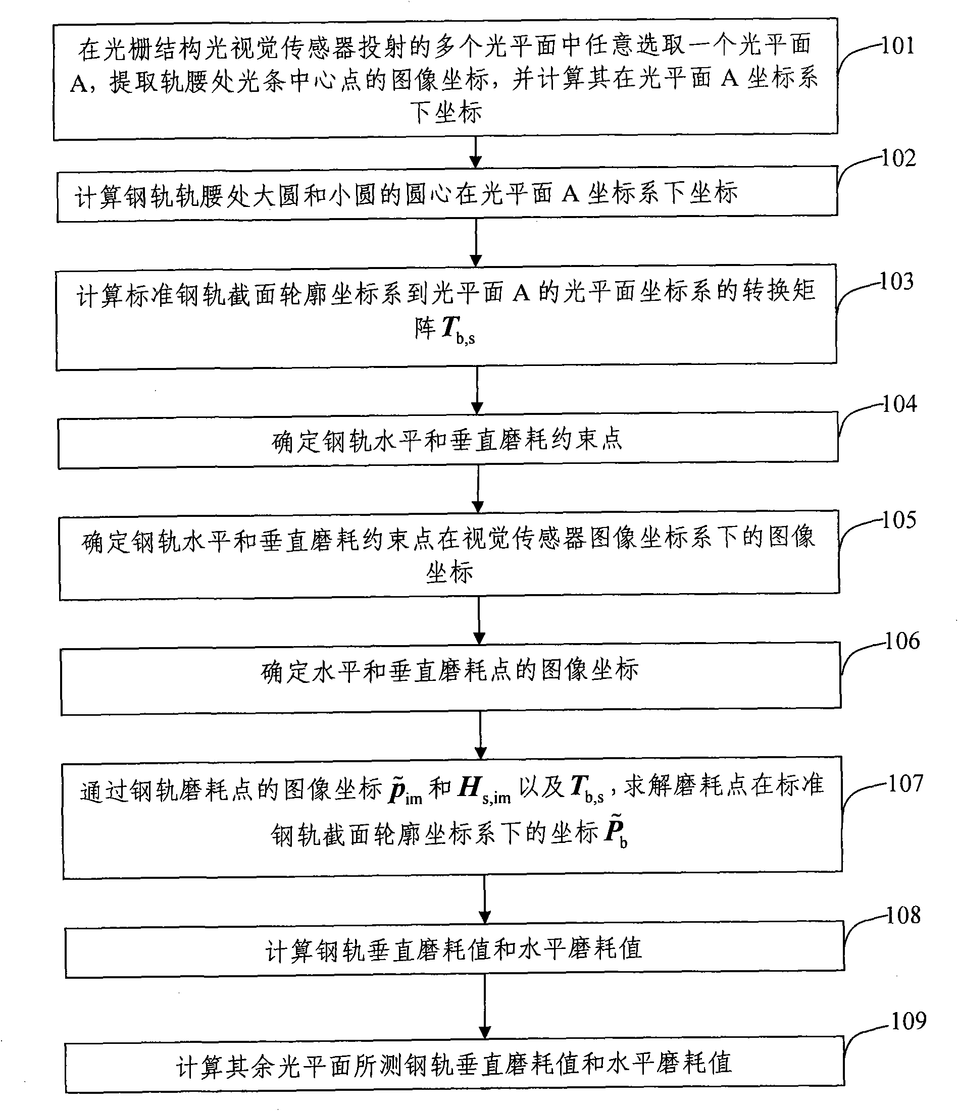
[0028] figure 1 For the flow chart of the method for quickly determining the rail wear value of the present invention, as figure 1 As shown, the rapid determination method of rail wear value of the present invention comprises the following steps:

[0029] Step 101: Randomly select a light plane A among the multiple light planes projected by the grating structured light vision sensor, and use Zhou Fuqiang et al. in the article "A Hybrid Image Processing Method for Extracting Structured Light Strips [J], Optoelectronics·Laser, 2008, 19(11): 1534-1537", the light strip extraction method mentioned in "extracts the image coordinates of the center point of the rail waist light strip.

[0030] According to the calibration method mentioned in the article "Field Calibration Method of Line Structured Light Vision Sensor [J], Chinese Journal of Mechanical Engineering, 2004, 40(6): 169-173" by Zhou Fuqiang et al. The ...


PUM


Abstract

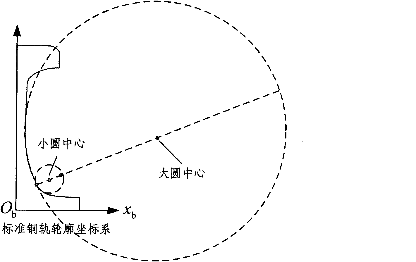
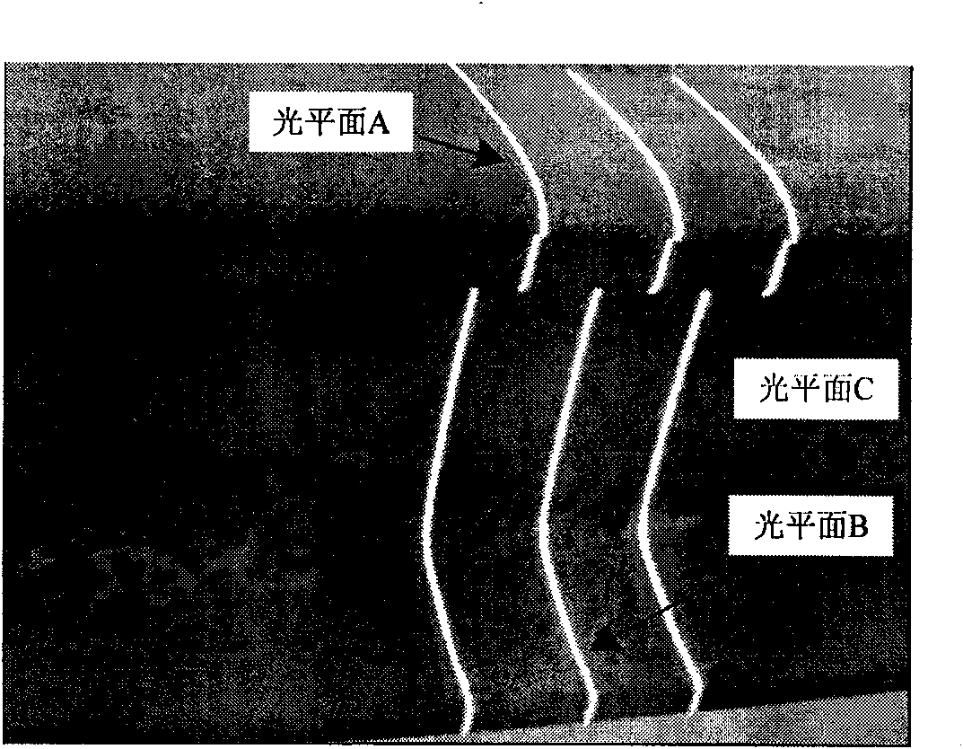
The invention discloses a fast processing method of a laser vision image of steel rail wear, comprising the following steps of: projecting more than two optical planes which are mutually parallel and vertical to the axial direction of the steel rail, selecting one optical plane and projecting the optical plane to images of the rail waist of the steel rail and an optical strip of the rail head, calculating a coordinate of the center of the optical strip at the rail waist in a coordinate system of the optical plane, and calculating circle center coordinates of large circles and small circles of the rail waist in the coordinate system of the optical plane; calculating a transformation matrix between the coordinate system of the selected optical plane and a profile coordinate system of the section of the standard steel rail; respectively determining intersection points of line segment and the optical strip of the rail head between the constraint points of vertical wear and the constraint points of horizontal wear in the image plane of a video sensor; carrying out inverse transformation on the image coordinate of the vertical wear point and horizontal wear point to the profile coordinate system of the section of the standard steel rail, and determining the coordinate of the vertical wear point and horizontal wear point of the steel rail in the profile coordinate system of the section of the standard steel rail, and the vertical distance and horizontal distance between the vertical wear point and the horizontal wear point of the steel rail and the profile of the standard steel rail, namely the wear value of the measured steel rail. The detection efficiency of the wear value of the steel rail is improved greatly.

Description

technical field [0001] The invention relates to a fast processing method for rail wear laser visual images. Background technique [0002] The condition of railways is closely related to safety, especially for high-speed trains. Regular inspection of rails is very important to plan properly and keep maintenance costs low. Measuring rail wear and deformation at an early stage can help create better maintenance schedules. In recent years, with the rapid increase of my country's railway speed, passenger and freight volume and traffic density, the wear and tear of rails has become increasingly serious. In order to meet the high-speed development of railway transportation, fast and high-precision measurement of rail wear is an important topic that railway departments at home and abroad have been studying deeply. [0003] According to different detection methods, the existing rail wear measurement devices can be roughly divided into contact type and non-contact type measurement ...

Claims


Application Information

Patent Timeline
IPC IPC(8): G01B11/03G01B11/24B61K9/08
Inventor 张广军刘震孙军华王伟华魏振忠
Owner BEIHANG UNIV
Learn More