
Detection control method of self-adapting tuning passive power filter

A technology of power filter and passive filter, which is applied to harmonic reduction devices and AC networks to reduce harmonics/ripples, etc., and can solve the problems of rare, filtering characteristics, grid frequency fluctuations and component parameter changes, and large Problems such as technical difficulty in capacity realization

Active Publication Date: 2009-11-11
STATE GRID ELECTRIC POWER RES INST
View PDF0 Cites 12 Cited by
  • Summary
  • Abstract
  • Description
  • Claims
  • Application Information

AI Technical Summary

Problems solved by technology

At present, the passive LC filter is the most widely used in the industrial field, but it has the disadvantages that it cannot be adjusted, the filtering characteristics are easily affected by the fluctuation of the grid frequency and component parameters, and it is easy to resonate with the system impedance, and it is difficult to adapt to the increasingly complex and changeable filter. power grid
Due to the high cost of active filters, the technical difficulty of realizing large capacity, and the difficulty in detection and control, there are not many examples of active filters that can run for a long time
Although the hybrid filter takes both economical and technical requirements into account, it also has obvious deficiencies. Between the power grid and the APF (active power filter) of the parallel hybrid active filter, and between the APF and the LC There are harmonic channels between the filters, which may cause the harmonics injected by the APF to flow into the LC filter and the power grid; the system stability and compensation effect of the series hybrid and series-parallel hybrid active filters are not easy to coordinate, and the compensation can be improved one-sidedly. The effect will make the system unstable, and the realization of system stability is achieved by sacrificing a certain compensation effect

Method used


Image

  • Detection control method of self-adapting tuning passive power filter
  • Detection control method of self-adapting tuning passive power filter
  • Detection control method of self-adapting tuning passive power filter

Examples


Embodiment Construction

[0021] The present invention will be further described below in conjunction with the accompanying drawings and embodiments.

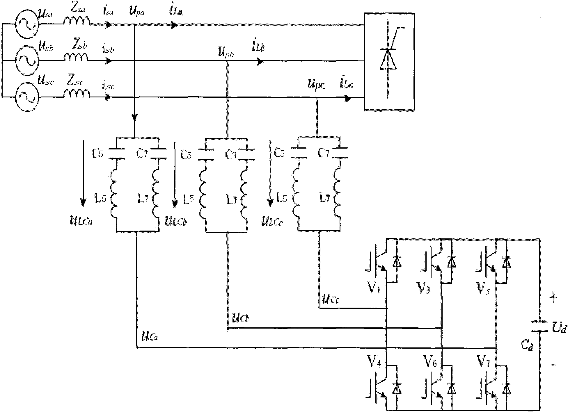
[0022] Figure 1 to Figure 4 The description is as follows:

[0023] u LCmj (m = a, b, c; j = 5, 7, 11) - its tuning subharmonic voltage,

[0024] u LCm (m=a,b,c) - the total voltage across the single-tuned LC passive filter,

[0025] u sm (m=a, b, c) - system voltage, Z sm (m=a, b, c) - system impedance,

[0026] i sm (m=a, b, c) - system current, i Lm (m=a, b, c)-load current,

[0027] u pm (m=a, b, c) - system common connection point voltage,

[0028] u LChm (m=a, b, c)-the sum of the tuning subharmonic voltages on each single-tuned LC passive filter,

[0029] C d - The DC side capacitor of the inverter, whose DC voltage is U d ,

[0030] u cm (m=a, b, c) - the compensation voltage generated by the inverter,

[0031] Please refer to figure 2 , the detection and control method of the self-adaptive tuning passive power filter of the...


PUM


Abstract

The invention relates to a detection control method of a self-adapting tuning passive power filter and provides a self-adapting tuning passive power filter, which comprises a single tuning LC passive filter and an inverter connected with the LC passive filter. The inverter is provided with a controller, and a drive unit is connected between the inverter and the controller; the voltage of the LC passive filter is detected in real time and input to a measuring unit of the controller; the measuring unit uses an instantaneous symmetrical component method and instantaneous reactive power theory to calculate tuning secondary voltage component that is then input to a compensation unit of the controller; the compensation unit uses a space vector modulation method to calculate the duty ratio required for generating compensating voltage and input the duty ratio to the drive unit; and the drive unit generates trigger pulse to control the work of the inverter to realize the self-adapting tuning, thus realizing the automatic follow-up tuning of electrical network frequency fluctuation and element parameter change. Besides, the inverter is small in volume, low in cost, adjustable in parameters and easy for being implemented industrially.

Description

technical field [0001] The invention belongs to the power filtering technology, and in particular relates to a detection and control method of an adaptive tuning passive power filter. Background technique [0002] In modern times, with the continuous increase of non-linear loads, the harmonic problem in the power system is becoming more and more serious, which has become one of the main factors affecting the power quality. There are mainly three types of harmonic control methods: passive LC filter, active filter and hybrid active filter (passive + active). At present, the passive LC filter is the most widely used in the industrial field, but it has the disadvantages that it cannot be adjusted, the filtering characteristics are easily affected by the fluctuation of the grid frequency and component parameters, and it is easy to resonate with the system impedance, and it is difficult to adapt to the increasingly complex and changeable filter. grid. Due to the high device cost...

Claims


Application Information

Patent Timeline
IPC IPC(8): H02J3/01
CPCY02E40/40
Inventor 冯宇
Owner STATE GRID ELECTRIC POWER RES INST
Learn More