Voltage limiting device

A voltage limiter and voltage technology, applied in the field of voltage devices, can solve problems such as limited application occasions, voltage restrictions, and difficulty in driving high-impedance earphones, and achieve the effects of simple implementation, small scale, and low power consumption

Inactive Publication Date: 2009-11-11
CREATIVE TECH CORP
View PDF12 Cites 5 Cited by
  • Summary
  • Abstract
  • Description
  • Claims
  • Application Information

AI Technical Summary

Problems solved by technology

[0006] But the weak point of above-mentioned prior art is that applicable occasions are all limited, and reason is as follows:
In this way, for a low-impedance earphone with an impedance of 32 ohms, the voltage required for its normal operation is only 180 millivolts. However, this voltage value has not yet reached the PN junction voltage drop of the diode, and the diode clamp circuit cannot limit its voltage. In addition, although high-impedance headphones require a voltage of 700 millivolts, which can be used in conjunction with a diode clamp circuit for protection, the audio source signal in most existing portable audio players is difficult to drive high-impedance headphones. Clamping circuits are also difficult to apply
[0008] In the FET analog switch circuit, the source signal is generally used to generate an analog switch control signal that varies with the source signal, and the control signal is loaded between the source and gate of the FET to make the gate-source voltage difference Greater or less than the turn-on voltage (or pinch-off voltage) of the FET, and then control the conduction and cut-off between the source and drain of the FET, thereby affecting the connectivity between the source and the load
However, if the source signal voltage cannot generate a variable analog switch control signal, the conduction state between the source and drain of the FET cannot be changed, and the FET analog switch circuit cannot normally perform voltage limiting work.

Method used


Image

  • Voltage limiting device
  • Voltage limiting device
  • Voltage limiting device

Examples


Embodiment Construction

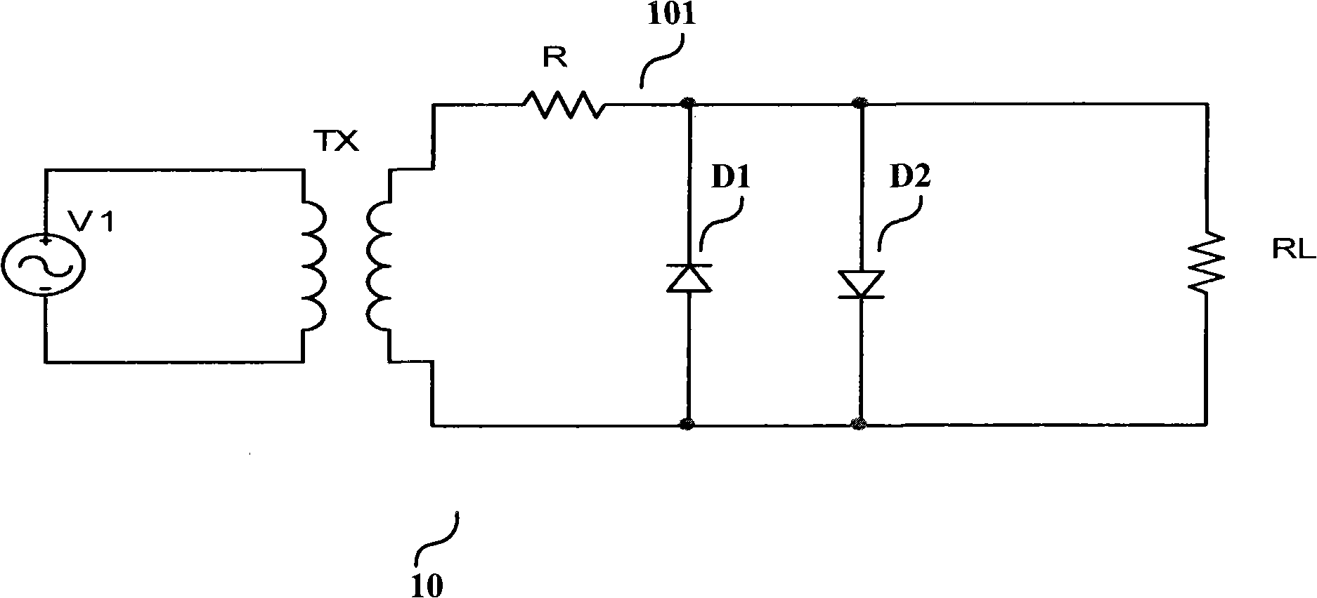
[0021] The following will be combined with figure 1 , 2 and 3 illustrate an aspect of the invention. figure 1 It is a circuit diagram of a diode-clamped voltage limiter with a transformer according to a specific embodiment of the present invention. The voltage limiter 10 is used for transforming and limiting the voltage of the signal provided by the audio signal source V1 to the audio reproduction device RL. It includes: a transformer TX, the primary coil of which is connected to the audio source V1, thereby transforming the signal provided by the audio source V1, and obtaining the transformed signal at the secondary coil; a diode clamp voltage limiting circuit 101 , consisting of a voltage dividing resistor R and a pair of antiparallel diodes D1 and D2, used to limit the voltage of the transformed signal to obtain a pressure-limited signal and provide it to the audio reproduction device RL.

[0022] The working principle of the diode clamp voltage limiting circuit 101 is a...


PUM


Abstract

The invention provides two circuits comprising transformers and used for limiting the voltage of weak electrical signals. The transformer of one of the two circuits transforms the voltage of a signal of an alternating-current information source, and a voltage limiting circuit limits a maximal voltage value of the signal with transformed voltage and then provides the maximal voltage value to a load; the transformer of the other circuit transforms a signal supplied by the alternating-current information source, a control circuit of an analog switch generates a control signal for switching the on or the off of the analog switch according to the size of the signal with transformed voltage and the on / off of the analog switch changes the connectivity of the load with the alternating-current information source and limits the load receiving the signal of the alternating-current information source. With a voltage limiting device of the invention, the voltage of the weal electrical signals, which is beyond a limiting range of the voltage limiting circuit, can be effectively limited, thereby the invention has easy realization, small scale and little power.

Description

technical field [0001] The invention relates to a device for limiting the voltage of a weak electric signal, in particular to a device for limiting the voltage of an audio signal obtained by an audio reproduction device from an audio source. Background technique [0002] The voltage limiting device is used to limit the voltage of the signal to not exceed a certain threshold before outputting it. It uses the source signal as input to judge whether the voltage of the signal exceeds a predetermined threshold. When the voltage of the source signal is lower than the predetermined threshold, the voltage limit The device does not limit the voltage amplitude of the source signal received by the load; when the source signal voltage is higher than the predetermined threshold, the voltage limiting device limits the voltage amplitude of the source signal, so that the source signal received by the load The voltage size is limited. [0003] In the prior art, a passive (no additional powe...

Claims


Application Information

Patent Timeline
Patent Type & Authority Applications(China)
IPC IPC(8): H03G11/00H03G11/02G10H1/00H04R3/00H03K17/687H03K17/60
Inventor 毕强董志栋沈小祥廖运钦
Owner CREATIVE TECH CORP
Why Eureka
Try Eureka