Method and apparatus for the heat treatment of welds

A welding direction and welding machine technology, applied in heat treatment furnaces, heat treatment equipment, induction heating, etc., can solve problems such as uneven temperature distribution, uneven weld height, etc., and achieve small temperature gradients and minimize the risk of tissue overheating Effect

Inactive Publication Date: 2009-11-11
SMS DEMAG AG
View PDF3 Cites 6 Cited by
  • Summary
  • Abstract
  • Description
  • Claims
  • Application Information

AI Technical Summary

Problems solved by technology

This results in a process-induced inhomogeneous temperature distribution and thus inhomogeneous heat treatment over the height of the weld seam

Method used


Image

  • Method and apparatus for the heat treatment of welds
  • Method and apparatus for the heat treatment of welds
  • Method and apparatus for the heat treatment of welds

Examples


Embodiment Construction

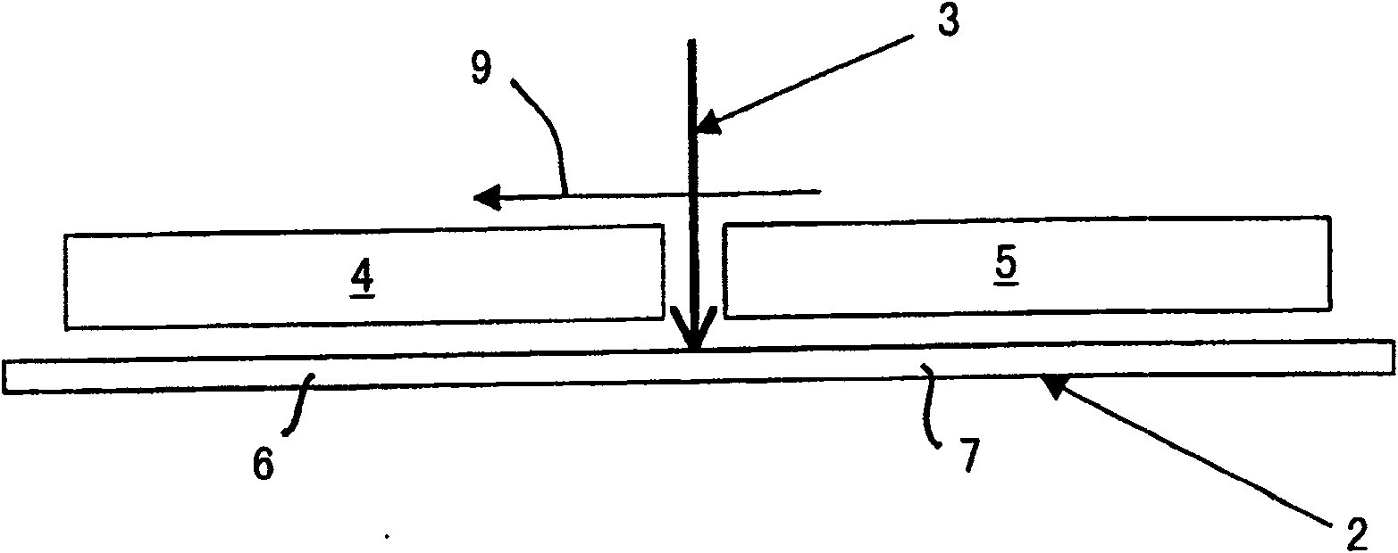
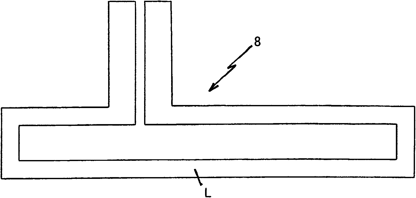
[0027] exist figure 1 The middle abbreviation shows the weld seam 1 for welding and for heat-treating steel strip 2 (see Figure 4 )installation. It consists of a laser welding head 3, a linear sensor 4 arranged in front of it, and a linear sensor 5 arranged behind it. In this exemplary embodiment, the laser welding head 3 and the two linear sensors 4 , 5 are moved in the direction of movement or welding 9 for the welding process and for the heat treatment, and firmly clamp the steel strip 2 . The exemplary embodiment shown here can also be used for movable steel sheets in a stationary arrangement of the linear inductors 4 , 5 and the laser welding head 3 . The linear sensor moving in front of the laser welding head 3 heats the steel strip 2 in the front moving weld seam 6 corresponding to the length of the linear sensor 4 and in the same way by the straight line moving behind the laser welding head 3. The sensor 5 heats the welding seam position 7 of the laser welding head...


PUM


Abstract

The present invention relates to a method and a device for the heat treatment of welds. To improve and further develop the heat treatment of the weld and the joining weld regions (6, 7) before and behind the actual welding by means of a laser, which is carried out during welding of steel sheets (2) to minimize the risk of crack formation or alteration of the microstructure in the region of the weld, it is proposed according to the invention that the heating of the region of the weld (6, 7) be carried out by means of a multiply stepped line inductor (4, 5) which can be set in a defined way and has zones of different power densities and is configured with a multiple division of its conductor loop lengths and/or with different plating of the conductor loops and/or with a plurality of spacing steps from the steel strip (2). Here, a steeper temperature rise occurs in the first heating stage than in the subsequent heating stage.

Description

technical field [0001] The invention relates to a method and a device for inductively heat-treating a weld seam in a welding machine with a laser welding head for joining the welding strips, wherein the weld seam and the associated weld seam are performed before and after the actual welding by means of linear sensors. The heating process adjacent to the weld seam. Background technique [0002] During welding, and especially during laser beam welding of thin sheets, very high energy is applied concentratedly in a very narrow region of the joining zone. Since the sheet metal area adjoining this intensely heated area is at ambient temperature, it cools down very rapidly at the end of the welding due to the high temperature drop. This results in tissue changes which significantly deteriorate the mechanical properties in this region. The cooling is therefore influenced after the welding process by targeted heat treatment of the relevant weld seam locations before and after the ...

Claims


Application Information

Patent Timeline
Patent Type & Authority Applications(China)
IPC IPC(8): C21D1/42C21D9/50H05B6/02B23K26/42B23K26/70
CPCY02P10/25
Inventor L·库梅尔H·贝伦斯C·伦格斯多夫R·朱根斯
Owner SMS DEMAG AG
Why Eureka
Try Eureka