Method and device for transferring gravity separation substances

A technology of gravity separation and transfer, applied in separation methods, liquid separation, chemical instruments and methods, etc., can solve the problems of difficult liquid level synchronization, large friction resistance of rubber sealing ring seals, inability to descend and ascend normally, etc. Reasonable structure design and simple method

Active Publication Date: 2009-11-18
大连迈克环境科技工程有限公司 +1
View PDF0 Cites 6 Cited by
  • Summary
  • Abstract
  • Description
  • Claims
  • Application Information

AI Technical Summary

Problems solved by technology

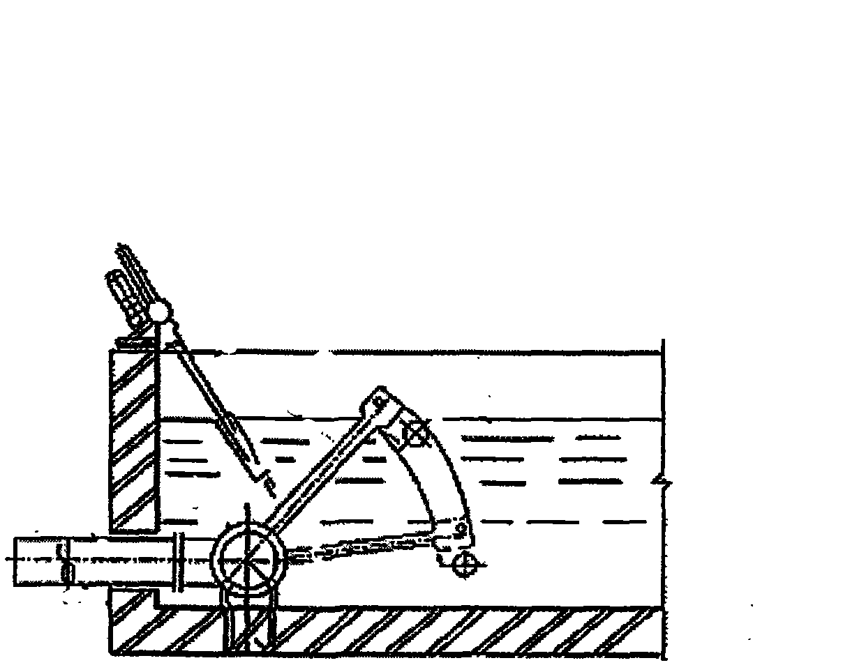
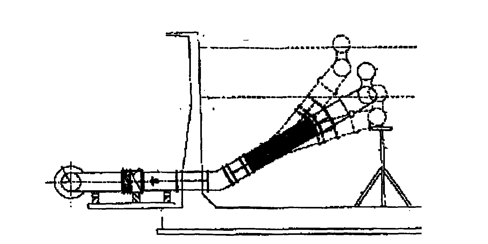
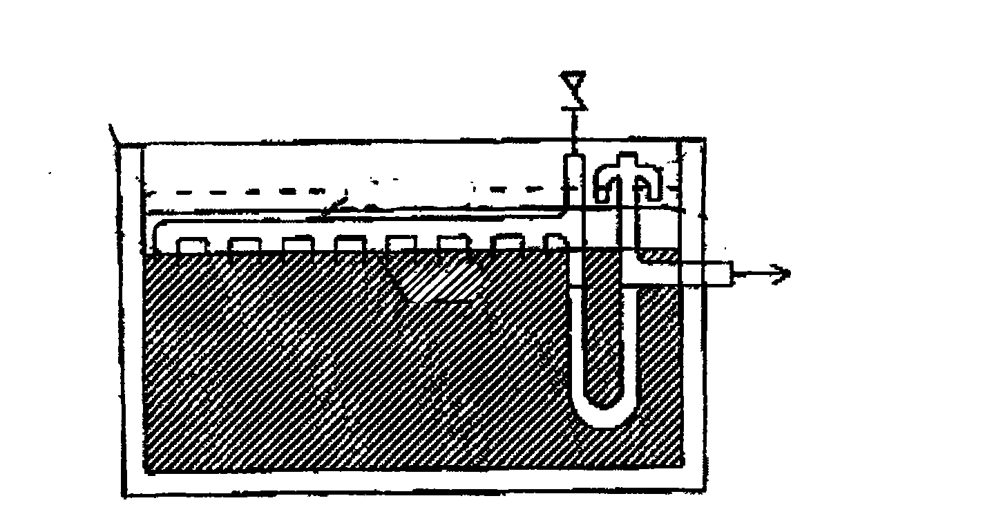
[0009] Siphon type: After the liquid level drops, it will cause a great disturbance to the layered interface, which will affect the pipetting effect of the pipette
[0010] Sleeve type: The inner and outer cylinders of the sleeve connecting the discharge pipe are sealed by an "L"-shaped rubber sealing ring, which requires a large-power motor and a reduce

Method used


Image

  • Method and device for transferring gravity separation substances
  • Method and device for transferring gravity separation substances
  • Method and device for transferring gravity separation substances

Examples


Example Embodiment

[0042] Example 1

[0043] Such as Figure 5-9The gravity separation removal device shown is mainly composed of a pontoon actuator 1, a weir plate 2, and a linear self-powered telescopic cylinder 3. The buoyancy generated by the pontoon actuator 1 is equal to that of the pontoon actuator, the weir plate and the linear self-powered telescopic cylinder in the liquid. The weir plate 2 is fixed and fitted on the outer wall surface of the upper end of the linear self-powered telescopic cylinder 3, and forms an opening and closing water inlet weir with the bottom surface of the buoy actuator 1. The upper end of the linear self-powered telescopic cylinder 3 is connected to the buoy actuator 1, and the linear self-powered telescopic Cylinder 3 is a sliding sleeve telescopic cylinder consisting of three sections of cylinders 3.1, 3.2 and 3.4 of different diameters. The adjacent cylinders can be sleeved relative to each other in turn. For example, the bottom end of the inner cylinder has a li...

Example Embodiment

[0044] Example 2

[0045] The device described in Example 1 is used for gravity separation. The specific process flow is as follows Picture 10 Shown: settlement, stratification-the weir plate is opened-the device and the liquid level drop simultaneously-the lowest liquid level weir plate is closed.

[0046] The first step is sedimentation or clarification: the solution undergoes physicochemical reactions or biological activities in the sedimentation or clarification structure, and the water inlet weir of the pipetting device is closed and kept at the high limit of the liquid level (such as Picture 11 );

[0047] The second step is layering and opening the pipetting device: the solution undergoes physicochemical reactions or biological activities in the sedimentation or clarification structure, and after a suitable period of time is stratified, the pipetting device moves downwards and the water inlet weir is opened (such as Picture 12 ), the layered supernatant slowly gradually ...


PUM


Abstract

The invention relates to a method and a device for water treatment. A device for transferring gravity separation substances mainly comprises a buoy execution mechanism, a weir plate and a linear self-operated telescopic cylinder, wherein the weir plate is fixedly sleeved on the outer wall surface at the upper end of the linear self-operated telescopic cylinder and forms a retractable water inlet weir crest with the bottom surface of the buoy execution mechanism, the upper end face of the linear self-operated telescopic cylinder is connected with the buoy execution mechanism, the linear self-operated telescopic cylinder is a sliding bush type telescopic cylinder with more than two sections, and a buoyancy generated by a floater equals to the gravity generated by the buoy execution mechanism, the weir plate and the linear self-operated telescopic cylinder in liquid. The execution mechanism of the device is simple, has low energy consumption, and is convenient to mount and repair. The weir plate adopts double-sealing precedence order, reliably prevents the disturbance of irregular fluid state entering the weir crest on the layered solution at the working initial stage of the device, and ensures the transfer of the layered supernatant. On the premise of ensuring sealing, the linear self-operated telescopic cylinder realizes synchronous rising or falling without an external force along with the liquid level, and ensures the stability and synchronous falling state of a layered level of the layered solution.

Description

1. Technical field: [0001] The invention relates to the field of environmental protection, in particular to a water treatment method, and also to water treatment equipment. 2. Background technology: [0002] Sedimentation or clarification process equipment is often used in the fields of water supply and sewage treatment, and oil-water separation. These process equipment are mainly used: the specific gravity of the polymer formed by adding physical and chemical agents and impurities in the water is greater than that of water; in the process of sedimentation or clarification, the stratification of the polymer or activated sludge and water is realized, and the purified water is in the upper layer. The polymer or activated sludge is in the lower layer, and then the upper layer water after stratification is removed by the pipetting device, so that the purified water can be discharged. In the same way, after the floating oil is separated, use a pipetting device to pipette and rec...

Claims


Application Information

Patent Timeline
IPC IPC(8): B01D17/032B01D21/24
Inventor 詹技灵A·戴德里奇斯
Owner 大连迈克环境科技工程有限公司
Why Eureka
Try Eureka