
Furnace top distributing gear

A technology of distributor and furnace top, which is applied to the field of furnace top distributor and furnace top distributor in ironmaking, can solve the problems of high cost of rotary bearing, complicated lubrication system, low transmission efficiency, etc., so as to save construction cost and maintenance cost. , Simple maintenance and repair, high transmission efficiency

Active Publication Date: 2011-04-06
CISDI ENG CO LTD
View PDF0 Cites 2 Cited by
  • Summary
  • Abstract
  • Description
  • Claims
  • Application Information

AI Technical Summary

Problems solved by technology

The distributor introduced in China is vertically installed with a planetary differential mechanism, and the output transmission of the concentric shaft meets the transmission requirements; the planetary differential mechanism, gears and worm wheels are installed vertically, and the lubrication system is complicated; the structure of the concentric output shaft is relatively Complex, and the size of the hollow shaft is large, and the seal is not easy; in order to meet the large transmission ratio requirements of the tilting chute, the previous stage of the central sun gear of the planetary differential mechanism is a worm gear transmission, which is used as the power source for the tilting of the chute. The connection of the tilting chute adopts gears to increase the transmission ratio and worm gear transmission, which not only has low transmission efficiency, but also has a small transmission ratio, which makes the slewing bearings and gears of the tilting mechanism suffer from greater force, resulting in higher requirements for slewing bearings and gears. Or use expensive imported parts, the cost of slewing bearings is expensive

Method used


Image

  • Furnace top distributing gear
  • Furnace top distributing gear
  • Furnace top distributing gear

Examples


Embodiment Construction

[0011] The present invention will be further described below in conjunction with accompanying drawing:

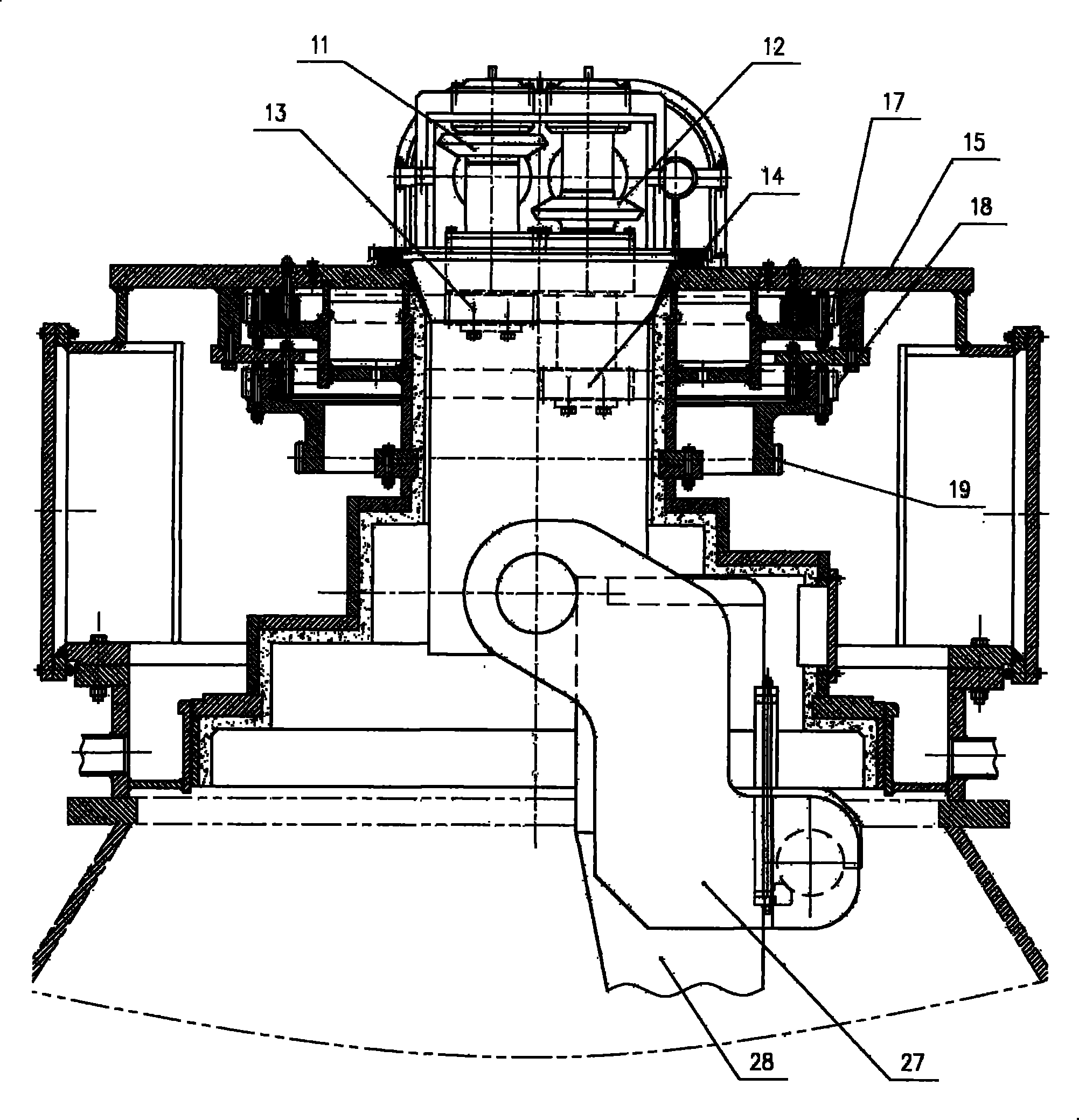
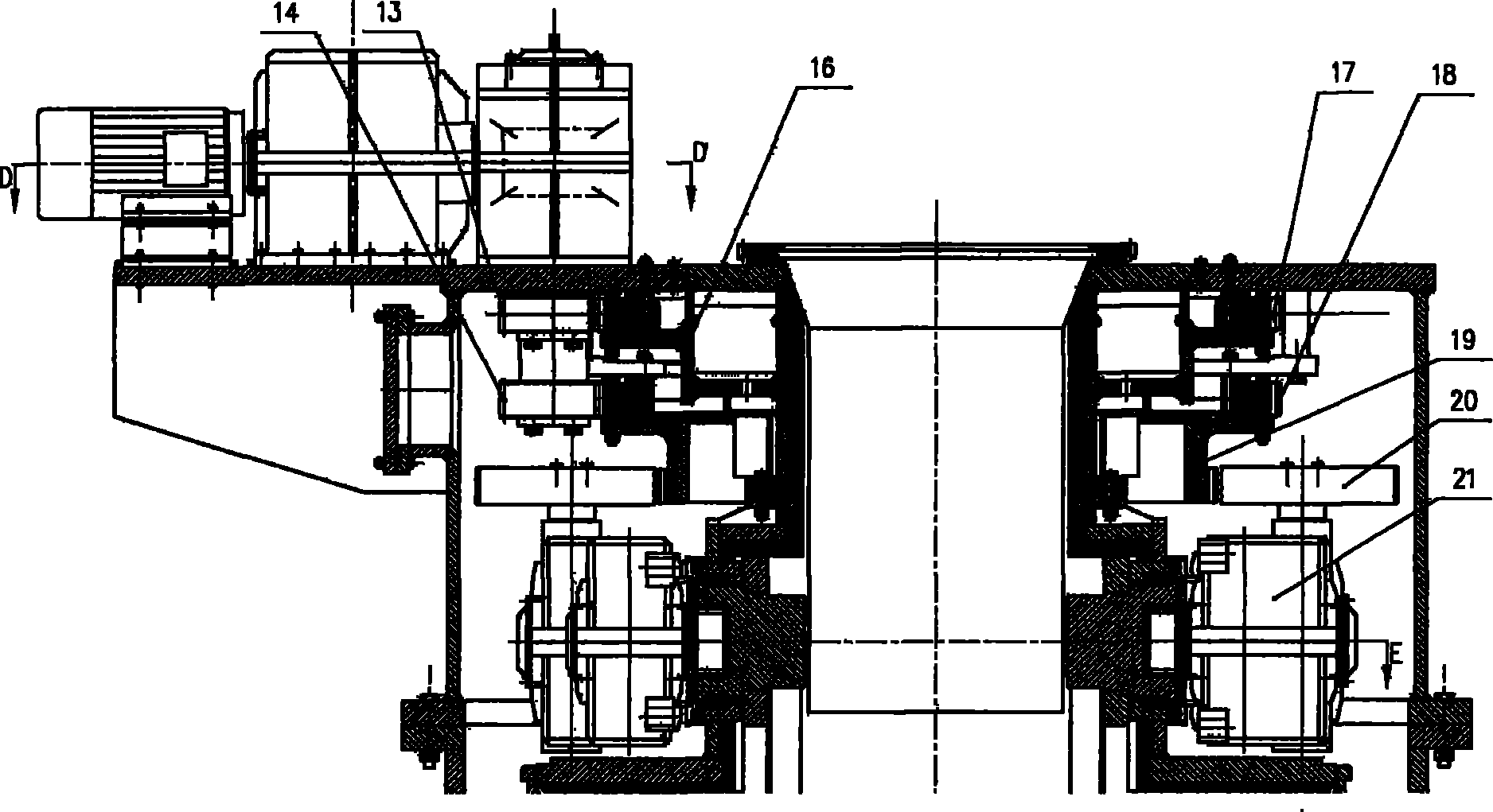
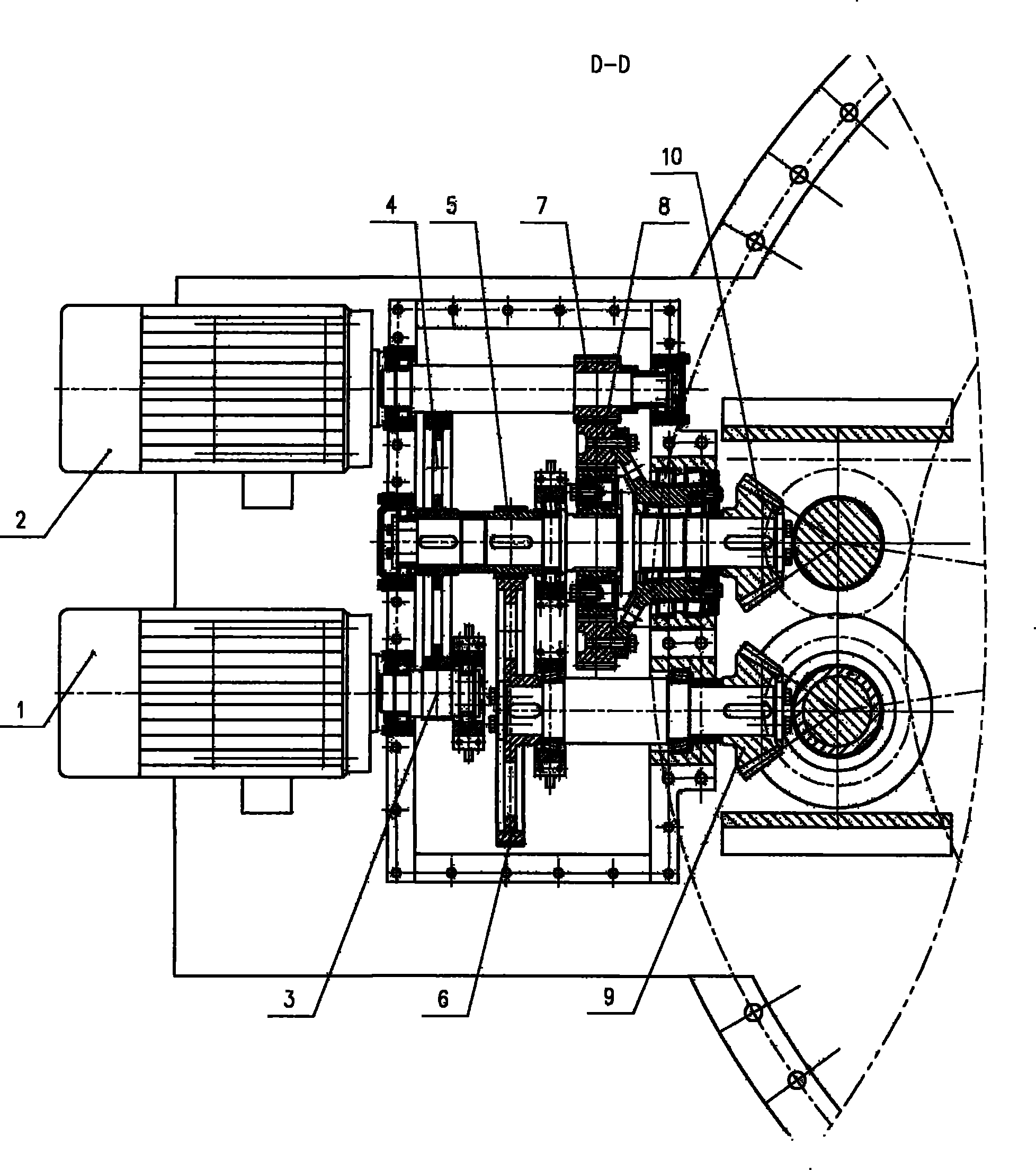
[0012] The output shaft of the rotating electrical machine 1 is fixedly connected concentrically with the gear 3, the gear 3 meshes with the gear 4, the gear 4 and the gear 5 are fixedly connected concentrically with the central sun gear shaft of the differential mechanism 8, the gear 5 meshes with the gear 6, and the gear 6 meshes with the bevel The gear 9 is concentrically fixedly connected, the gear 7 meshes with the outer teeth of the ring gear of the differential mechanism 8, the bevel gear 10 is concentrically fixedly connected with the planet carrier of the differential mechanism 8, the bevel gear 9 meshes with the bevel gear 11, and the bevel gear 10 meshes with the bevel gear 12 meshes, the bevel gear 11 is concentrically fixedly connected with the rotary mechanism input gear 13, the bevel gear 12 is concentrically fixedly connected with the tilting mechanism input ...


PUM


Abstract

The invention discloses a furnace top distributing gear for distributing materials on the top of an iron-fining furnace, belonging to the technical field of mechanical engineering. A rotating motor and a tilting motor are independently driven by a set of differential mechanisms, wherein differential mechanism drive and previous-stage drive adopt all-gear drive, the previous-stage drive of a central sun wheel of the differential mechanism adopts gear drive with common drive ratio, and a furnace pot is tilted by a three-ring speed reducer. The furnace top distributing gear can realize the functions of furnace pot tilting, furnace pot rotation and furnace pot tilting and rotation, has the advantages of compact structure, reliable drive, stable work, high drive efficiency, long service life, little maintaining workload and convenient furnace pot replacement, can be used for blast furnace engineering of various types or other places where loose unpacked materials are delivered.

Description

technical field [0001] The invention belongs to the technical field of mechanical engineering and discloses a furnace top distributor, in particular a furnace top distributor for ironmaking. Background technique [0002] The ironmaking furnace top distributor is the core equipment of the ironmaking furnace top. At present, the distributors used in China are almost imported foreign equipment, especially large blast furnaces. The distributor introduced in China is vertically installed with a planetary differential mechanism, and the output transmission of the concentric shaft meets the transmission requirements; the planetary differential mechanism, gears and worm wheels are installed vertically, and the lubrication system is complicated; the structure of the concentric output shaft is relatively Complex, and the size of the hollow shaft is large, and the sealing is not easy; in order to meet the large transmission ratio requirements of the tilting chute, the previous stage o...

Claims


Application Information

Patent Timeline
Patent Type & Authority Patents(China)
IPC IPC(8): C21B7/00
Inventor 马云峰陈宗源赵渭康彭学元王涛
Owner CISDI ENG CO LTD
Learn More