
Driving device of industrial sewing machine

A driving device and sewing machine technology, applied in the direction of sewing machine control devices, sewing machine components, sewing machine housings, etc., can solve the problems of complex structure of the tension adjustment unit, increase in the number of assembly processes, and large operating force, etc., to reduce the number of components and The number of parts, the ease of assembly work, and the effect of simplifying the structure

Inactive Publication Date: 2009-11-18
YAMATO SEWING MASCH MFG CO LTD
View PDF0 Cites 7 Cited by
  • Summary
  • Abstract
  • Description
  • Claims
  • Application Information

AI Technical Summary

Problems solved by technology

[0004] However, in the belt tension adjustment unit disclosed in Patent Document 1, in addition to the motor mounting plate, it is necessary to substantially fix the bracket supporting the motor, and to attach the bracket to the motor mounting plate in a rotatable and fixed manner. Screw shafts such as a plurality of bolts, a plurality of screw holes formed on the pallet for screwing and fixing these screw shafts, adjustment screws and other adjusting parts for rotating and fixing the pallet relative to the motor mounting plate, etc. The number of components and parts, and the structure of the tension adjustment unit are very complicated
As a result, not only the number of assembly steps of the drive unit as a whole increases, but also a lot of troublesome work is done when adjusting the belt tension after assembly.
In addition, when adjusting the belt tension, the heavy weight of the motor generates a load as a rotational moment centered on a screw shaft, and it is necessary to overcome this load moment to operate adjustment components such as the adjusting screw, so there is a possibility that belt tension adjustment requires a large operation. force problem

Method used


Image

  • Driving device of industrial sewing machine
  • Driving device of industrial sewing machine
  • Driving device of industrial sewing machine

Examples


Embodiment Construction

[0017] Embodiments of the present invention will be described below with reference to the drawings.

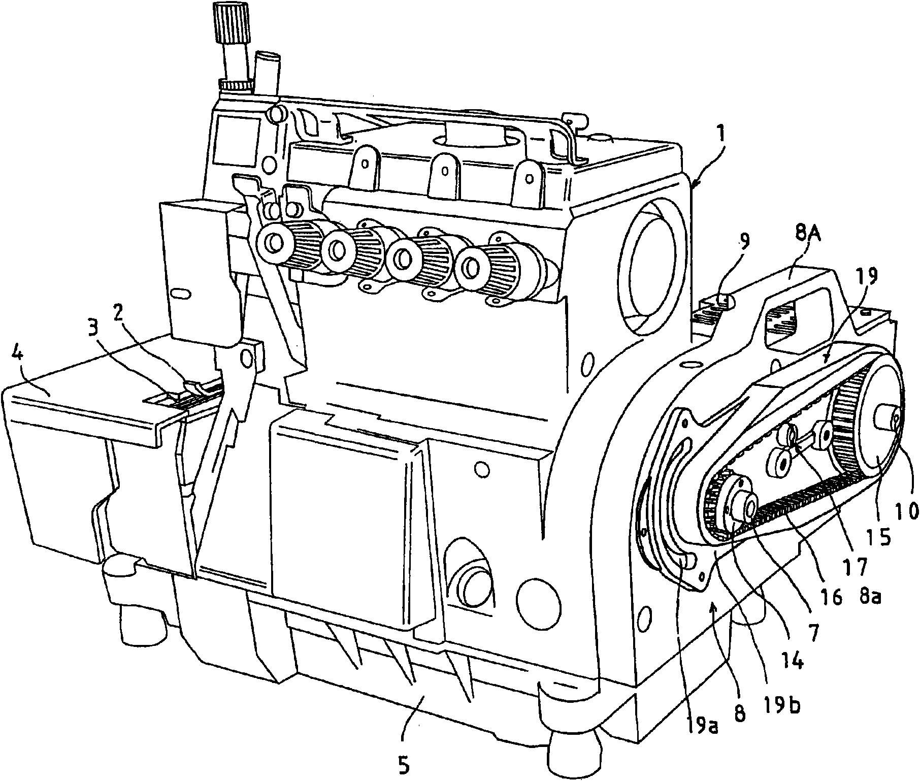
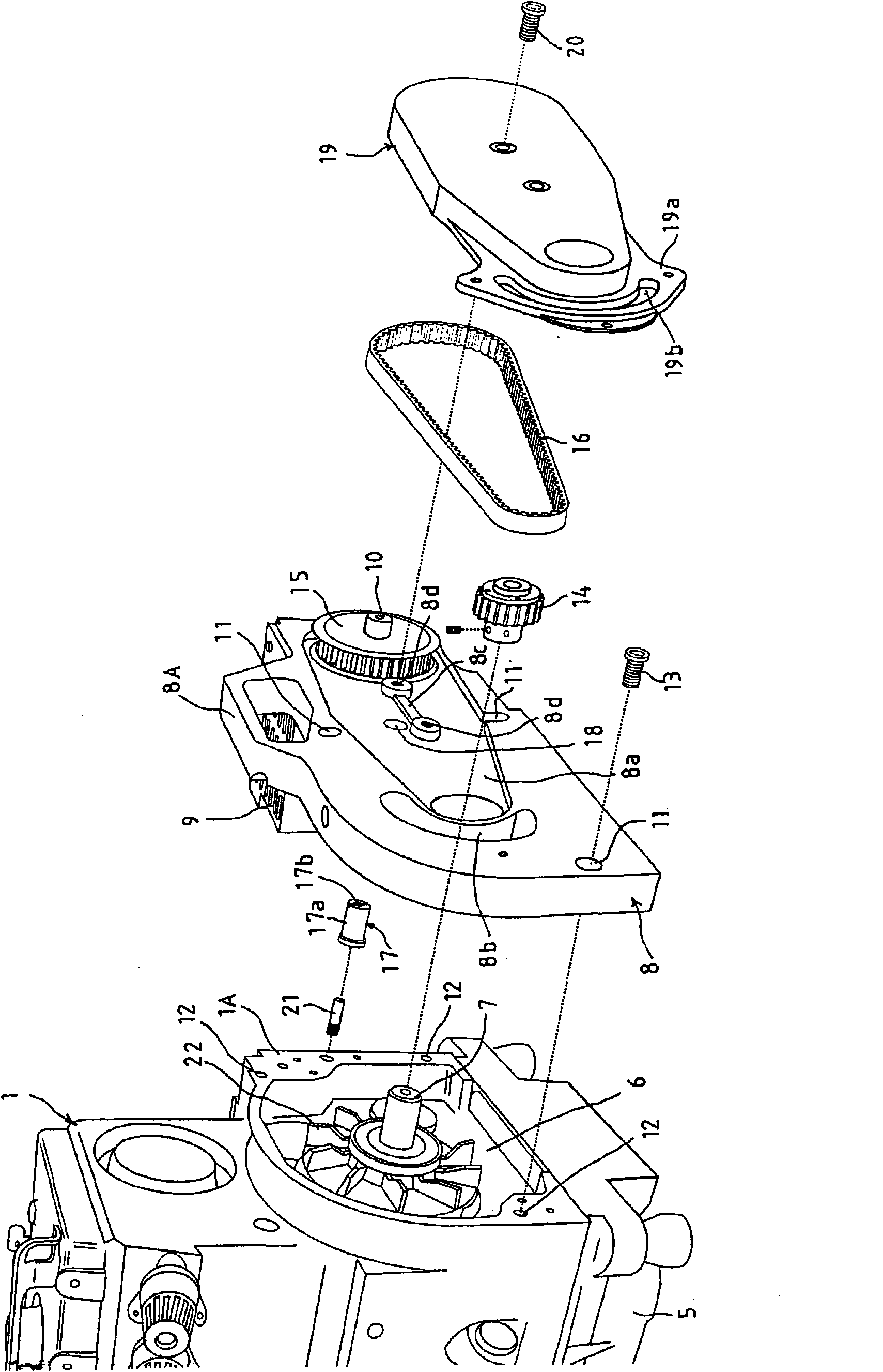
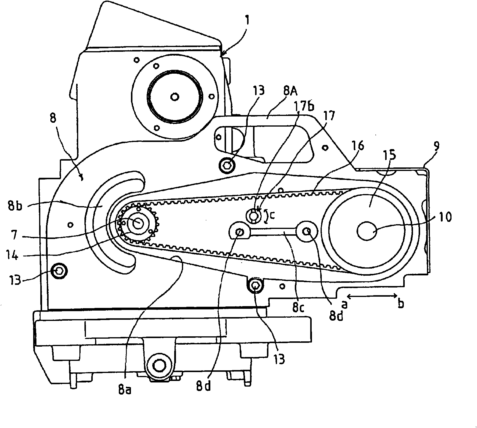
[0018] figure 1 It is an overall perspective view of an overlock sewing machine to which a driving device for an industrial sewing machine according to the present invention is applied, figure 2 is an exploded perspective view of the main parts, image 3 for the right view. In these Figure 1 ~ Figure 3 Among them, symbol 1 is the main body of the sewing machine, on its left side is provided with a needle (because it is known, so its description is omitted), a presser foot 2, a feed dog 3 and a looper (because it is known, so its description is omitted) on its left side. A sewing platform (clothplate) 4 and the like are installed in the sewing machine body 1, and a lubricating oil storage part 5 called an oil pan is installed at the lower end of the sewing machine body 1.

[0019] A substantially semidome-shaped recessed portion 6 that opens outward is formed at a right e...


PUM


Abstract

The present invention provides a driving device of an industrial sewing machine. A main shaft of the sewing machine projects outwards from the side part of the main body of sewing machine. An installation table of an electric motor extends from the side surface part of the main body of sewing machine backwards. The main shaft of the sewing machine and the output shaft of a sewing machine driving motor which is fixedly connected with the back part of the installation table of the electric motor. The side surface part of the main body of sewing machine is equipped with an eccentric cam. The installation table of the electric motor is formed with an opening with the inner peripheral part which slideably contact with the outer peripheral part of the eccentric cam. The position of the installation table of the electric motor is changed through rotating the eccentric cam, and the tension of the synchronous belt can be adjusted thereby obtaining the following advantages: reducing the number of constituent elements and components as possible, simplifying the structure, reducing the number of whole assembling steps of the device, reducing the troubles for adjusting the belt tension, and easily and smoothly operating the device with a small operating force.

Description

technical field [0001] The present invention relates to a driving device for an industrial sewing machine such as an overlock sewing machine, and more specifically, to a driving device for an industrial sewing machine having a structure in which a main shaft of the sewing machine protrudes outward from a side of the main body of the sewing machine, and a motor mounting table is disposed on the side of the main body of the sewing machine. The main shaft of the sewing machine and the output shaft of the motor for driving the sewing machine fixedly supported at the rear of the motor mounting table are hung on the side part and the rear part of the sewing machine main body through the toothed pulley fixed on the two shafts and wound. The toothed belts between these toothed pulleys are interlockingly connected, and at the same time, a mounting table fixing unit such as a bolt is provided between the motor mounting table and the sewing machine body, and the mounting table fixing unit...

Claims


Application Information

Patent Timeline
IPC IPC(8): D05B69/10D05B73/00
Inventor 水崎隆德田奈穗子彌永明夫
Owner YAMATO SEWING MASCH MFG CO LTD
Learn More