
Device and method for measurement while drilling of ground stress

A technology of measurement while drilling and in-situ stress, which is applied in the direction of measurement, earthwork drilling, wellbore/well components, etc., which can solve the problems of unusability and achieve the effects of short time, convenient use and accurate measurement

Inactive Publication Date: 2009-11-18
INST OF MECHANICS - CHINESE ACAD OF SCI
View PDF0 Cites 23 Cited by
  • Summary
  • Abstract
  • Description
  • Claims
  • Application Information

AI Technical Summary

Problems solved by technology

Because as the drill pipe is pulled out, the soft coal seam coal chips on the wall of the measuring hole will collapse into the measuring hole, blocking the hole, and the pressure sensor cannot be placed, so this method cannot be used to measure the ground stress of the soft coal seam

Method used


Image

  • Device and method for measurement while drilling of ground stress
  • Device and method for measurement while drilling of ground stress
  • Device and method for measurement while drilling of ground stress

Examples


Embodiment 1

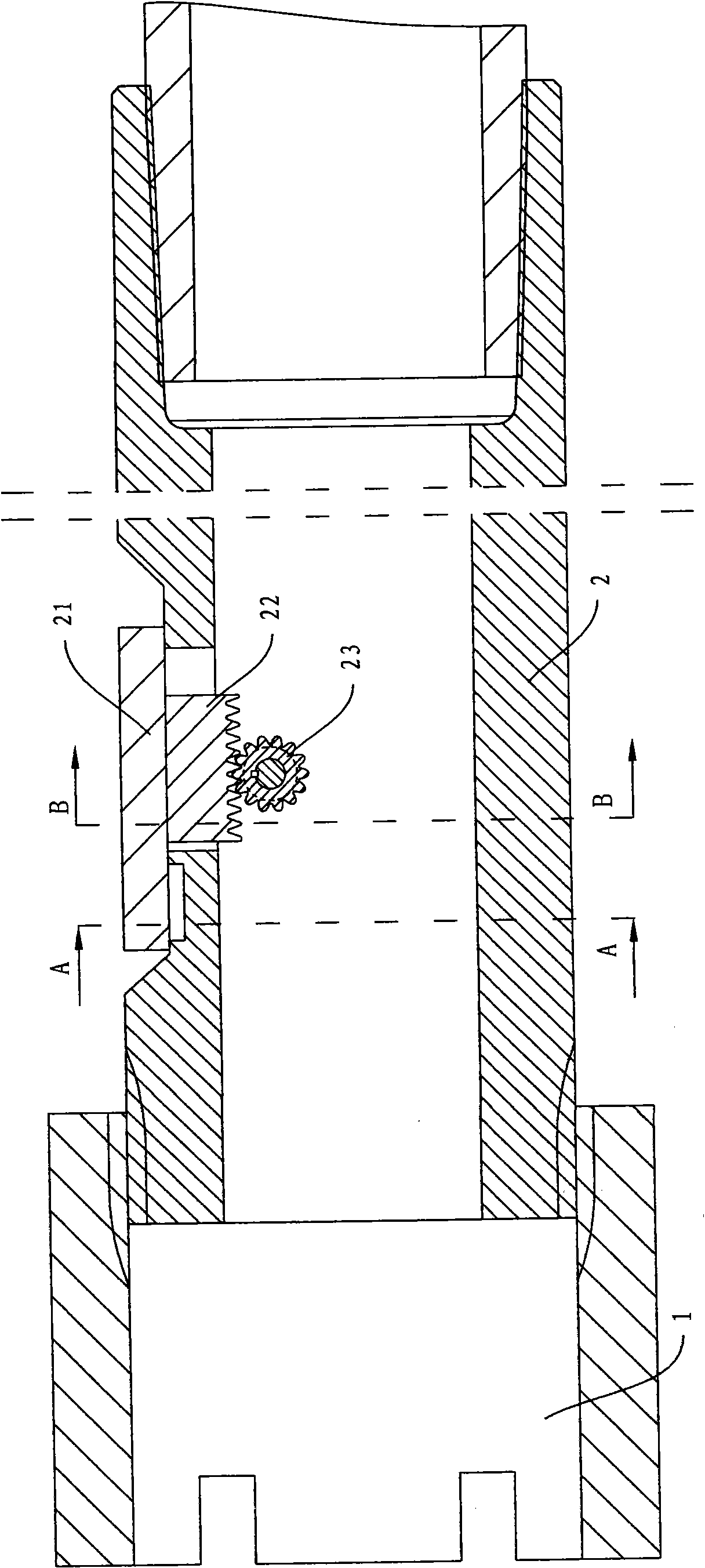
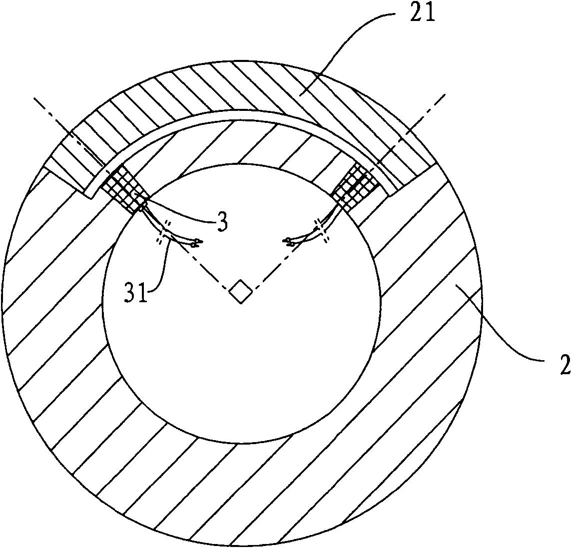
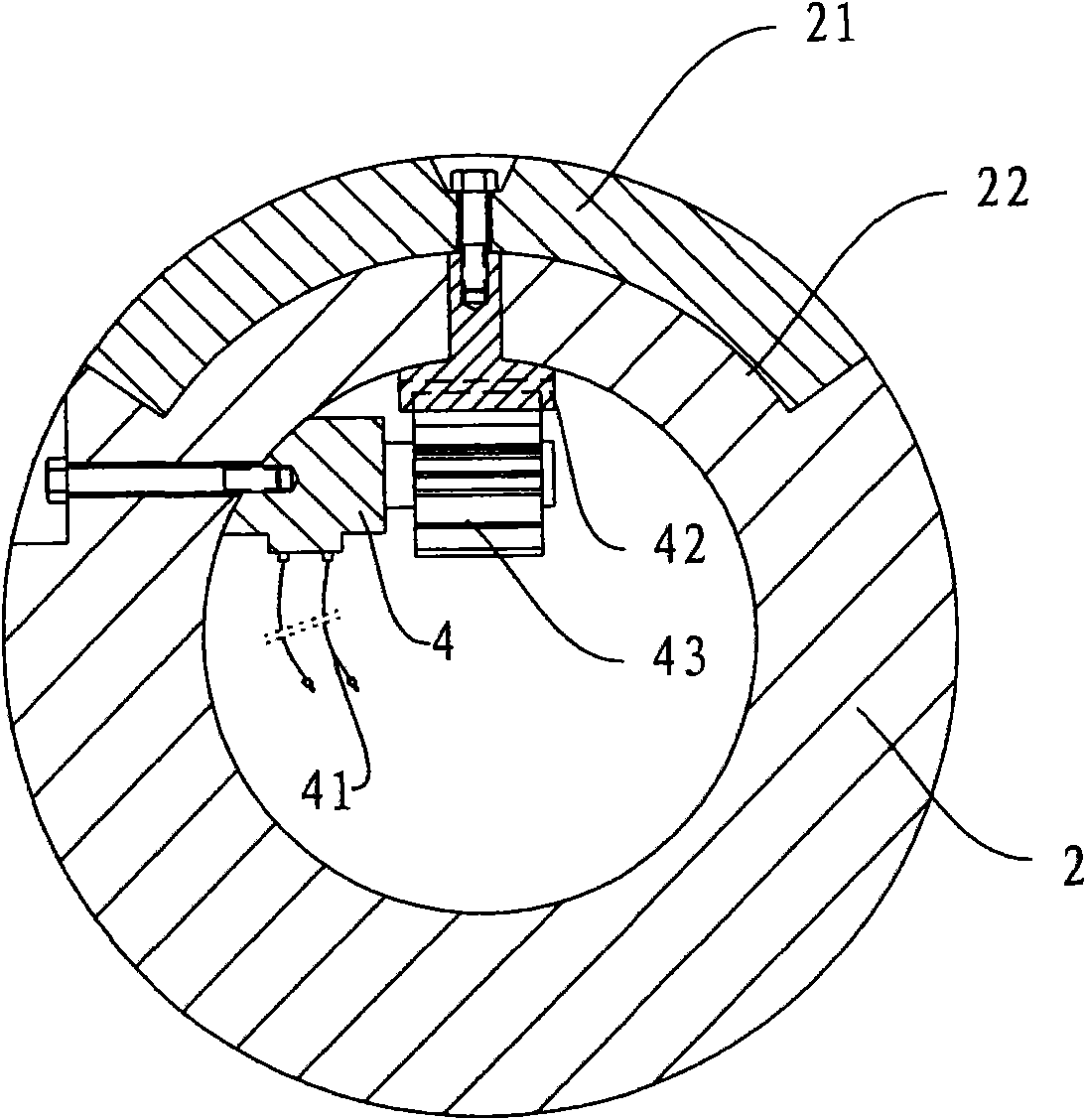
[0023] Such as Figure 1 to Figure 3 As shown, the embodiment of the present invention provides a kind of in-situ stress measurement-while-drilling device, including a drilling machine (not shown in the figure), a drill pipe 2 and a drill bit 1, and the side wall close to the drill bit 1 on the drill pipe 2 connected to the drill bit 1 A pressure sensor 3 is arranged on the drill pipe 2, and a slide cover 21 for protecting the pressure sensor 3 is also provided on the drill pipe 2. When the slide cover 21 slides open, the pressure sensor 3 can be exposed. When the slide cover 21 is closed, the pressure sensor 3 can be covered by the slide cover. 21 is closed, and the sliding cover 21 realizes sliding opening and closing by a driving device. There are two pressure sensors 3 with an included angle of 90°, which can measure the ground stress in X and Y directions. Each pressure sensor 3 is provided with a data line 31, and the connection terminal is a plug mode, which is conveni...

Embodiment 2

[0026] An embodiment of the present invention provides a method for measuring in-situ stress while drilling, comprising the following steps:

[0027] 1) Select the position that needs to be measured on the downhole working face, and use the in-situ stress measurement-while-drilling device described in Embodiment 1 to construct the borehole according to the designed borehole inclination, azimuth, depth and aperture. At this time, keep the slide cover 21 is closed;

[0028] 2) Stop the machine after drilling the hole, separate the drill pipe 2 from the drilling rig, then connect the pressure sensor 3 directly to the signal processing device (not shown in the figure), and then connect various other circuits, and then pass through the driving device of the slide cover 21 Sliding the slide cover 21 to expose the pressure sensor 3;

[0029] Specifically, the sliding cover 21 is driven to slide open by controlling the motor 4 to drive the gear 43 and the rack 42 mechanism.

[0030]...


PUM


Abstract

The invention discloses a device for the measurement while drilling of ground stress, which comprises a drill, a drill rod and a drill head, wherein the side wall, close to the drill head, of the drill rod connected with the drill head is provided with a pressure sensor; and the drill rod is also provided with a sliding cover protecting the pressure sensor; and the sliding cover slides open and closes through a driving device. The invention also discloses a method for the measurement while drilling of ground stress, which comprises the following steps: selecting a position to be measured and performing drilling construction by using the device for the measurement while drilling of ground stress; stopping a machine after drilling, separating the drill rod from the drill, directly connecting the pressure sensor with a signal processing unit, and sliding the sliding cover open to expose the pressure sensor by using the sliding cover driving device; and measuring the ground stress of a coal bed by using the pressure sensor. The device and the method can measure the ground stress while drilling, be used underground conveniently, allow for continuous, accurate and quick measurement in a measurement hole and measure the ground stress of soft coal beds.

Description

technical field [0001] The invention relates to an in-situ stress measuring device and method, in particular to an in-situ stress measuring-while-drilling device and method. Background technique [0002] In mining engineering, it is often encountered that mine pressure appears due to excessive structural stress, so the measurement of ground stress in the coal seam is often carried out along with the development, excavation and coal mining. However, the current measurement method is to follow the measurement method in rock mechanics, that is, first use a drilling rig to drill a hole in the coal seam at the depth to be measured, then pull out the drill pipe, put the pressure sensor into the measured hole, and then use clay To fill the measurement hole, it is necessary to wait until the pressure in the measurement hole reaches equilibrium before measuring the accurate ground stress through the pressure sensor, and the waiting time for the pressure in the hole to reach equilibri...

Claims


Application Information

Patent Timeline
Patent Type & Authority Applications(China)
IPC IPC(8): E21B47/12E21B47/06E21B49/00
CPCE21B47/017
Inventor 张均锋
Owner INST OF MECHANICS - CHINESE ACAD OF SCI
Learn More